
Edition 1
Abstract
DHCP, BIND, and DNS.
DHCP and DNS servers from the Part II, “Servers” section. Most of the non-networking related material from the Red Hat Enterprise Linux 6 Deployment Guide guide can now be found in the Fedora 20 System Administrator's Guide except for reference material, such as that found in the appendices of the Deployment Guide. Reference material is now in a separate guide, the Fedora 20 System Administrator's Reference Guide.
nmtui, is also available.
nmcli connection reload command. Changes made through NetworkManager's D-Bus API or with nmcli are still effective immediately.
DHCP) server and client. Read this chapter if you need to configure DHCP on your system.
DNS), explains how to install, configure, run, and administer the BIND DNS server. Read this chapter if you need to configure a DNS server on your system.
NTP) and Precision Time Protocol (PTP), see the Fedora 20 System Administrator's Guide.
Mono-spaced Bold
To see the contents of the filemy_next_bestselling_novelin your current working directory, enter thecat my_next_bestselling_novelcommand at the shell prompt and press Enter to execute the command.
Press Enter to execute the command.Press Ctrl+Alt+F2 to switch to a virtual terminal.
mono-spaced bold. For example:
File-related classes includefilesystemfor file systems,filefor files, anddirfor directories. Each class has its own associated set of permissions.
Choose → → from the main menu bar to launch Mouse Preferences. In the Buttons tab, select the Left-handed mouse check box and click to switch the primary mouse button from the left to the right (making the mouse suitable for use in the left hand).To insert a special character into a gedit file, choose → → from the main menu bar. Next, choose → from the Character Map menu bar, type the name of the character in the Search field and click . The character you sought will be highlighted in the Character Table. Double-click this highlighted character to place it in the Text to copy field and then click the button. Now switch back to your document and choose → from the gedit menu bar.
Mono-spaced Bold Italic or Proportional Bold Italic
To connect to a remote machine using ssh, typessh username@domain.nameat a shell prompt. If the remote machine isexample.comand your username on that machine is john, typessh john@example.com.Themount -o remount file-systemcommand remounts the named file system. For example, to remount the/homefile system, the command ismount -o remount /home.To see the version of a currently installed package, use therpm -q packagecommand. It will return a result as follows:package-version-release.
Publican is a DocBook publishing system.
mono-spaced roman and presented thus:
books        Desktop   documentation  drafts  mss    photos   stuff  svn
books_tests  Desktop1  downloads      images  notes  scripts  svgs
mono-spaced roman but add syntax highlighting as follows:
package org.jboss.book.jca.ex1;
import javax.naming.InitialContext;
public class ExClient
{
public static void main(String args[])
throws Exception
{
InitialContext iniCtx = new InitialContext();
Object ref = iniCtx.lookup("EchoBean");
EchoHome home = (EchoHome) ref;
Echo echo = home.create();
System.out.println("Created Echo");
System.out.println("Echo.echo('Hello') = " + echo.echo("Hello"));
}
}Note
Important
Warning
networking-guide
20
Table of Contents
NetworkManager, then NetworkManager's command-line tool nmcli, and then finally methods using the command line and configuration files. The command line can be used to issue commands and to compose or edit configuration files, therefore the use of the ip commands and configuration files will be documented together.
NetworkManager, which is a dynamic network control and configuration daemon that attempts to keep network devices and connections up and active when they are available. The traditional ifcfg type configuration files are still supported. See Section 1.6, “NetworkManager and the Network Scripts” for more information.
Table 1.1. A Summary of Networking Tools and Applications
| Application or Tool | Description |
|---|---|
| NetworkManager | The default networking daemon |
| nmtui | A simple curses-based text user interface (TUI) for NetworkManager |
| nmcli | A command-line tool provided to allow users and scripts to interact with NetworkManager |
| control-center | A graphical user interface tool provided by the GNOME Shell |
| nm-connection-editor | A GTK+ 3 application available for certain tasks not yet handled by control-center |
NetworkManager can be used with the following types of connections: Ethernet, VLANs, Bridges, Bonds, Teams, Wi-Fi, mobile broadband (such as cellular 3G), and IP-over-InfiniBand. For these connection types, NetworkManager can configure network aliases, IP addresses, static routes, DNS information, and VPN connections, as well as many connection-specific parameters. Finally, NetworkManager provides an API via D-Bus which allows applications to query and control network configuration and state.
root user:
~]# yum install NetworkManager~]$ systemctl status NetworkManager
NetworkManager.service - Network Manager
Loaded: loaded (/lib/systemd/system/NetworkManager.service; enabled)
Active: active (running) since Fri, 08 Mar 2013 12:50:04 +0100; 3 days agosystemctl status command will report NetworkManager as Active: inactive (dead) if the NetworkManager service is not running. To start it for the current session run the following command as the root user:
~]# systemctl start NetworkManagersystemctl enable command to ensure that NetworkManager starts up every time the system boots:
~]# systemctl enable NetworkManagercontrol network and then press Enter.
control network and then press Enter. The Super key appears in a variety of guises, depending on the keyboard and other hardware, but often as either the Windows or Command key, and typically to the left of the Spacebar.
network connections or nm-connection-editor and then press Enter.
man ip(8) page. The package name in Fedora is iproute. If necessary, you can check that the ip utility is installed by checking its version number as follows:
~]$ ip -V
ip utility, iproute2-ss130716Note
/etc/init.d/network and any other installed scripts it calls. The user supplied files are typically viewed as configuration, but can also be interpreted as an amendment to the scripts.
systemctl start|stop|restart|status network/etc/init.d/servicename start|stop|restart|status directly.
/etc/init.d/network checks with NetworkManager to avoid tampering with NetworkManager's connections. NetworkManager is intended to be the primary application using sysconfig configuration files and /etc/init.d/network is intended to be secondary, playing a fallback role.
/etc/init.d/network script is not event-driven, it runs either:
systemctl commands start|stop|restart networksystemctl enable network).
ifup and ifdown manually.
/sbin/ifup-local, ifdown-pre-local, and ifdown-local are only executed when those devices are controlled by the /etc/init.d/network service. If you modified the initscripts themselves (for example, /etc/sysconfig/network-scripts/ifup-eth) then those changes would be overwritten by an initscripts package update. Therefore it is recommend that you avoid modifying the initscripts directly and make use of the /sbin/if*local scripts, so that your custom changes will survive package updates. The initscripts just check for the presence of the relevant /sbin/if*local and run them if they exit. The initscripts do not place anything in the /sbin/if*local scripts, nor does the initscripts RPM (or any package) own or modify those files.
ifup and ifdown script will ask NetworkManager whether NetworkManager manages the interface in question, which is found from the “DEVICE=” line in the ifcfg file. If NetworkManager does manage that device, and the device is not already connected, then ifup will ask NetworkManager to start the connection.
ifdown" and the device is managed by NetworkManager, then ifdown will ask NetworkManager to terminate the connection.
/etc/sysconfig/ directory is a location for configuration files and scripts. Most network configuration information is stored there, with the exception of VPN, mobile broadband and PPPoE configuration, which are stored in /etc/NetworkManager/ subdirectories. Interface specific information for example, is stored in ifcfg files in the /etc/sysconfig/network-scripts/ directory.
/etc/sysconfig/network is for global settings. Information for VPNs, mobile broadband and PPPoE connections is stored in /etc/NetworkManager/system-connections/.
ifcfg file, NetworkManager is not automatically aware of the change and has to be prompted to notice the change. If you use one of the tools to update NetworkManager profile settings, then NetworkManager does not implement those changes until you reconnect using that profile. For example, if configuration files have been changed using an editor, NetworkManager must be told to read the configuration files again. To do that, issue the following command as root:
~]# nmcli connection reload
The above command reads all connection profiles. Alternatively, to reload only one changed file, ifcfg-ifname, issue a command as follows:
~]# nmcli con load /etc/sysconfig/network-scripts/ifcfg-ifname
The command accepts multiple file names. These commands require root privileges. For more information on user privileges and gaining privileges, see the Fedora 20 System Administrator's Guide and the su(1) and sudo(8) man pages.
nmcli dev disconnect interface-nameFollowed by:
nmcli con up interface-name
ifup commands are used. See Section 1.6, “NetworkManager and the Network Scripts” for an explanation of the network scripts.
ifup script is a generic script which does a few things and then calls interface-specific scripts like ifup-ethX, ifup-wireless, ifup-ppp, and so on. When a user runs ifup eth0 manually, the following occurs:
ifup looks for a file called /etc/sysconfig/network-scripts/ifcfg-eth0;
ifcfg file exists, ifup looks for the TYPE key in that file to determine which type-specific script to call;
ifup calls ifup-wireless or ifup-eth or ifup-XXX based on TYPE;
IP-related tasks like DHCP or static setup.
/etc/init.d/network reads through all the ifcfg files and for each one that has ONBOOT=yes, it checks whether NetworkManager is already starting the DEVICE from that ifcfg file. If NetworkManager is starting that device or has already started it, nothing more is done for that file, and the next ONBOOT=yes file is checked. If NetworkManager is not yet starting that device, the initscripts will continue with their traditional behavior and call ifup for that ifcfg file.
ifcfg file that has ONBOOT=yes is expected to be started on system bootup, either by NetworkManager or by the initscripts. This ensures that some legacy network types which NetworkManager does not handle (such as ISDN or analog dialup modems) as well as any new application not yet supported by NetworkManager are still correctly started by the initscripts even though NetworkManager is unable to handle them.
Note
ifcfg files in the same location as the live ones. The script literally does ifcfg-* with an exclude only for these extensions: .old, .orig, .rpmnew, .rpmorig, and .rpmsave. The best way is not to store backup files anywhere within the /etc/ directory.
man(1) man page — Describes man pages and how to find them.
NetworkManager(8) man page — Describes the network management daemon.
NetworkManager.conf(5) man page — Describes the NetworkManager configuration file.
/usr/share/doc/initscripts-version/sysconfig.txt — Describes configuration files and their directives.
IP addressing on those servers and devices whose network availability you want to ensure when automatic assignment methods, such as DHCP, fail. DHCP, DNS, and authentication servers are typical examples. Interfaces for out-of-band management devices are also worth configuring with static settings as these devices are supposed to work, as far as is possible, independently of other network infrastructure.
IP addressing is still considered desirable, use an automated provisioning method when possible. For example, DHCP servers can be configured to provide the same IP address to the same host every time. This method could be used for communal printers for example.
IP addresses manually. The nmcli tool is also suitable for use with scripted assignment of network configuration.
IP addresses and other network information whenever there is no compelling reason not to. The time saved in planning and documenting manual settings can be better spent elsewhere. The dynamic host control protocol (DHCP) is a traditional method of dynamically assigning network configurations to hosts. See Section 9.1, “Why Use DHCP?” for more information on this subject.
DHCP client, dhclient, automatically.
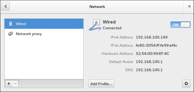
control network and then press Enter. The Network settings tool appears. Proceed to Section 2.2.2, “Configuring New and Editing Existing Connections”
IP address and routing details, and so on.
IP addressing, DNS, and routing configuration.
Procedure 2.1. Configuring NetworkManager to Connect to a Network Automatically When Detected
control network and then press Enter. The Network settings tool appears.
nm-settings(5) man page for more information on the connection settings permissions property. The permissions correspond to the USERS directive in the ifcfg files. If the USERS directive is not present, the network profile will be available to all users. As an example, the following command in an ifcfg file will make the connection available only to the users listed: USERS="joe bob alice"This can also be set using graphical user interface tools. In nm-connection-editor, there is the corresponding All users may connect to this network check box on the General tab, and in the GNOME control-center Network settings Identity window, there is the Make available to other users check box.
user creates a connection profile user-em2 with the Connect Automatically check box selected but with the Make available to other users not selected, then the connection will not be available at boot time.
polkit(8) man page for more information on polkit.
Procedure 2.2. Changing a Connection to Be User-specific Instead of System-Wide, or Vice Versa
control network and then press Enter. The Network settings tool appears.
root password to finalize the change.
control network and then press Enter. The Network settings tool appears.
1500 and does not generally need to be specified or changed.
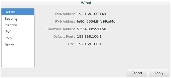
IPv4 settings for the connection, click the IPv4 Settings tab and proceed to Section 2.2.10.4, “Configuring IPv4 Settings”; or,
IPv6 settings for the connection, click the IPv6 Settings tab and proceed to Section 2.2.10.5, “Configuring IPv6 Settings”.
control network and then press Enter. The Network window appears. Select Wi-Fi from the menu and then select Connect to Hidden Network to cause a dialog to appear. If you have connected to the hidden network before, use the Connection dropdown to select it, and click . If you have not, leave the Connection dropdown as , enter the SSID of the hidden network, select its Wi-Fi security method, enter the correct authentication secrets, and click .
control network and then press Enter. The Network settings tool appears.
ip addr command will show the MAC address associated with each interface. For example, in the following ip addr output, the MAC address for the wlan0 interface (which is 00:1c:bf:02:f8:70) immediately follows the link/ether keyword:
~]# ip addr
1: lo: <LOOPBACK,UP,LOWER_UP> mtu 16436 qdisc noqueue state UNKNOWN
    link/loopback 00:00:00:00:00:00 brd 00:00:00:00:00:00
    inet 127.0.0.1/8 scope host lo
    inet6 ::1/128 scope host
       valid_lft forever preferred_lft forever
2: eth0: <BROADCAST,MULTICAST,UP,LOWER_UP> mtu 1500 qdisc pfifo_fast state UNKNOWN qlen 1000
    link/ether 52:54:00:26:9e:f1 brd ff:ff:ff:ff:ff:ff
    inet 192.168.122.251/24 brd 192.168.122.255 scope global eth0
    inet6 fe80::5054:ff:fe26:9ef1/64 scope link
       valid_lft forever preferred_lft forever
3: wlan0: <BROADCAST,MULTICAST,UP,LOWER_UP> mtu 1500 qdisc mq state UP qlen 1000
    link/ether 00:1c:bf:02:f8:70 brd ff:ff:ff:ff:ff:ff
    inet 10.200.130.67/24 brd 10.200.130.255 scope global wlan0
    inet6 fe80::21c:bfff:fe02:f870/64 scope link
valid_lft forever preferred_lft foreverip addr command, and then copy and paste that value into the MAC address text-entry field.
IPv4 settings for the connection, click IPv4 and proceed to Section 2.2.10.4, “Configuring IPv4 Settings”; or,
IPv6 settings for the connection, click IPv6 and proceed to Section 2.2.10.5, “Configuring IPv6 Settings”.
Procedure 2.3. Adding a New VPN Connection
control network and then press Enter. The Network settings tool appears.
Procedure 2.4. Editing an Existing VPN Connection
control network and then press Enter. The Network settings tool appears.
IP address of the remote VPN gateway.
IPv4 settings for the connection, click the IPv4 Settings tab and proceed to Section 2.2.10.4, “Configuring IPv4 Settings”.
Procedure 2.5. Adding a New Mobile Broadband Connection
nm-connection-editor and then press Enter. The Network Connections tool appears.
Procedure 2.6. Editing an Existing Mobile Broadband Connection
nm-connection-editor and then press Enter. The Network Connections tool appears.
IPv4 settings for the connection, click the IPv4 Settings tab and proceed to Section 2.2.10.4, “Configuring IPv4 Settings”; or,
IPv6 settings for the connection, click the IPv6 Settings tab and proceed to Section 2.2.10.5, “Configuring IPv6 Settings”.
Procedure 2.7. Adding a New DSL Connection
nm-connection-editor and then press Enter. The Network Connections tool appears.
Procedure 2.8. Editing an Existing DSL Connection
nm-connection-editor and then press Enter. The Network Connections tool appears.
IPv4 settings for the connection, click the IPv4 Settings tab and proceed to Section 2.2.10.4, “Configuring IPv4 Settings”.
DHCP servers were configured not to lease IP addresses to unauthorized users, but for various reasons this practice is both impractical and insecure, and thus is no longer recommended. Instead, 802.1X security is used to ensure a logically-secure network through port-based authentication.
control network and then press Enter. The Network settings tool appears. Proceed to Procedure 2.9, “For a Wired Connection” or Procedure 2.10, “For a Wireless Connection”:
Procedure 2.9. For a Wired Connection
Procedure 2.10. For a Wireless Connection
IP address, route, and DNS information as required. The IPv4 Settings tab is available when you create and modify one of the following connection types: wired, wireless, mobile broadband, VPN or DSL. If you need to configure IPv6 addresses, see Section 2.2.10.5, “Configuring IPv6 Settings”. If you need to configure static routes, click the button and proceed to Section 2.2.10.6, “Configuring Routes”.
DHCP to obtain a dynamic IP address from a DHCP server, you can simply set Method to .
Available IPv4 Methods by Connection Type
IPv4 connection methods. All of the methods are listed here according to which connection type, or types, they are associated with:
DHCP server to assign IP addresses. You do not need to fill in the DHCP client ID field.
DHCP server to assign IP addresses but you want to assign DNS servers manually.
DHCP server and you do not want to assign IP addresses manually. Random addresses will be assigned as per RFC 3927 with prefix 169.254/16.
10.42.x.1/24 range, a DHCP server and DNS server are started, and the interface is connected to the default network connection on the system with network address translation (NAT).
IPv4 is disabled for this connection.
IP addresses manually.
IP address and DNS servers automatically.
IP address automatically, but you want to manually specify DNS servers.
IP address and DNS servers automatically.
IP address automatically, but you want to manually specify DNS servers.
IP address and DNS servers automatically.
IP address automatically, but you wish to manually specify DNS servers.
IPv6 settings for this connection.
DHCP server to assign IP addresses but you want to assign DNS servers manually.
DHCP server and you want to assign IP addresses manually.
DHCP server and you do not want to assign IP addresses manually. Random addresses will be assigned as per RFC 4862 with prefix FE80::0.
DNS servers.
DHCP, an address of a gateway that leads to an upstream network or the Internet is usually assigned. This gateway is usually referred to as the default gateway as it is the gateway to use if no better route is known to the system (and present in the routing table). Network administrators often use the first or last host IP address in the network as the gateway address; for example, 192.168.10.1 or 192.168.10.254. Not to be confused by the address which represents the network itself; in this example, 192.168.10.0, or the subnet's broadcast address; in this example 192.168.10.255.
IP address of a remote network, sub-net, or host.
IP address entered above.
IP address of the gateway leading to the remote network, sub-net, or host entered above.
RA or DHCP are used, but you can also add additional static routes. When OFF, only static routes you define are used.
ifcfg-name, where the suffix name refers to the name of the device that the configuration file controls. By convention, the ifcfg file's suffix, ethX, is the same as the string given by the DEVICE directive in the configuration file itself.
ifcfg files, for an interface with name eth0, create a file with name ifcfg-eth0 in the /etc/sysconfig/network-scripts/ directory as follows:
DEVICE=eth0
BOOTPROTO=none
ONBOOT=yes
NETMASK=255.255.255.0
IPADDR=10.0.1.27
NM_CONTROLLED=no
Optionally specify the hardware or MAC address using the
HWADDR directive. Note that this will influence the device naming procedure as explained in Chapter 8, Consistent Network Device Naming. You do not need to specify the broadcast address as this is calculated automatically by ipcalc.
ifcfg files, for an interface with name em1, create a file with name ifcfg-em1 in the /etc/sysconfig/network-scripts/ directory as follows:
DEVICE=em1
BOOTPROTO=dhcp
ONBOOT=yes
NM_CONTROLLED=no
Optionally specify the hardware or MAC address using the
HWADDR directive. Note that this will influence the device naming procedure as explained in Chapter 8, Consistent Network Device Naming. You do not need to specify the broadcast address as this is calculated automatically by ipcalc.
IP addresses to an interface. The command takes the following form: ip addr [ add | del ] address dev ifname
IP address to an interface, issue a command as root as follows:
~]#Further examples and command options can be found in theip address add 10.0.0.3/24 dev eth0The address assignment of a specific device can be viewed as follows: ~]#ip addr show dev eth02: eth0: <BROADCAST,MULTICAST,UP,LOWER_UP> mtu 1500 qdisc pfifo_fast state UP qlen 1000 link/ether f0:de:f1:7b:6e:5f brd ff:ff:ff:ff:ff:ff inet 10.0.0.3/24 brd 10.0.0.255 scope global global eth0 valid_lft 58682sec preferred_lft 58682sec inet6 fe80::f2de:f1ff:fe7b:6e5f/64 scope link valid_lft forever preferred_lft forever
ip-address(8) manual page.
~]#ip address add 192.168.2.223/24 dev eth1~]#ip address add 192.168.4.223/24 dev eth1~]#ip addr3: eth1: <BROADCAST,MULTICAST,UP,LOWER_UP> mtu 1500 qdisc pfifo_fast state UP qlen 1000 link/ether 52:54:00:fb:77:9e brd ff:ff:ff:ff:ff:ff inet 192.168.2.223/24 scope global eth1 inet 192.168.4.223/24 scope global eth1
ip(8) manual page.
Note
ip route command to display the IP routing table. If static routes are required, they can be added to the routing table by means of the ip route add command and removed using the ip route del command. To add a static route to a host address, that is to say to a single IP address, issue the following command as root:
ip route add 192.0.2.1where 192.0.2.1 is the
IP address of the host in dotted decimal notation. To add a static route to a network, that is to say to an IP address representing a range of IP addresses, issue the following command as root:
ip route add 192.0.2.0/24where 192.0.2.0 is the
IP address of the network in dotted decimal notation and /24 is the network prefix. The network prefix is the number of enabled bits in the subnet mask. This format of network address slash prefix length is referred to as CIDR notation.
/etc/sysconfig/network-scripts/route-interface file. For example, static routes for the eth0 interface would be stored in the /etc/sysconfig/network-scripts/route-eth0 file. The route-interface file has two formats: ip command arguments and network/netmask directives. These are described below.
/etc/sysconfig/network file first and then the network interface ifcfg files for interfaces that are “up”. The ifcfg files are parsed in numerically ascending order, and the last GATEWAY directive to be read is used to compose a default route in the routing table.
DEFROUTE=no command in the ifcfg files for those interfaces which do not lead to the default gateway.
/etc/sysconfig/network file. This file specifies gateway and host information for all network interfaces. For more information about this file and the directives it accepts, see the Fedora 20 System Administrator's Reference Guide.
/etc/sysconfig/network-scripts/ directory. The file name should be of the format route-ethX. There are two types of commands to use in the configuration files; ip commands as explained in Section 2.3.4, “ Static Routes Using the IP Command Arguments Format ” and the Network/Netmask format as explained in Section 2.3.4, “ Network/Netmask Directives Format”.
/etc/sysconfig/network-scripts/route-eth0, define a route to a default gateway on the first line. This is only required if the gateway is not set via DHCP and is not set globally in the /etc/sysconfig/network file:
default via 192.168.1.1 dev interfaceIP address of the default gateway. The interface is the interface that is connected to, or can reach, the default gateway. The dev option can be omitted, it is optional. Note that this setting takes precedence over a setting in the /etc/sysconfig/network file.
10.10.10.0/24 via 192.168.1.1 dev interfaceIP address and interface for the gateway leading to the remote network. Add as many static routes as required.
route-eth0 file using the ip command arguments format. The default gateway is 192.168.0.1, interface eth0 and a leased line or WAN connection is available at 192.168.0.10. The two static routes are for reaching the 10.10.10.0/24 network and the 172.16.1.10/32 host:
default via 192.168.0.1 dev eth0
10.10.10.0/24 via 192.168.0.10 dev eth0
172.16.1.10/32 via 192.168.0.10 dev eth0
192.168.0.0/24 network will be directed out the interface attached to that network. Packets to unknown, remote, networks will use the default gateway. Below is an example of setting static routes to a different network, on a machine in the 192.168.0.0/24 network. The example machine has an eth0 interface in the 192.168.0.0/24 network, and an eth1 interface (with address 10.10.10.1) in the 10.10.10.0/24 network:
10.10.10.0/24 via 10.10.10.1 dev eth1
Duplicate default gateways
DHCP, the ip command arguments format can cause one of two errors during start-up, or when bringing up an interface from the down state using the ifup command: "RTNETLINK answers: File exists" or 'Error: either "to" is a duplicate, or "X.X.X.X" is a garbage.', where X.X.X.X is the gateway, or a different IP address. These errors can also occur if you have another route to another network using the default gateway. Both of these errors are safe to ignore.
route-interface files. The following is a template for the network/netmask format, with instructions following afterwards:
ADDRESS0=10.10.10.0 NETMASK0=255.255.255.0 GATEWAY0=192.168.1.1
ADDRESS0=10.10.10.0 is the network address of the remote network or host to be reached.
NETMASK0=255.255.255.0 is the netmask for the network address defined with ADDRESS0=10.10.10.0.
GATEWAY0=192.168.1.1 is the default gateway, or an IP address that can be used to reach ADDRESS0=10.10.10.0
route-eth0 file using the network/netmask directives format. The default gateway is 192.168.0.1, interface eth0. The two static routes are for reaching the 10.10.10.0/24 and 172.16.1.0/24 networks. This example is not necessary as traffic trying to reach a remote network or host would use the default gateway anyway:
ADDRESS0=10.10.10.0
NETMASK0=255.255.255.0
GATEWAY0=192.168.0.1
ADDRESS1=172.16.1.0
NETMASK1=255.255.255.0
GATEWAY1=192.168.0.1
ADDRESS0, ADDRESS1, ADDRESS2, and so on.
192.168.0.0/24 network. The example machine has an eth0 interface in the 192.168.0.0/24 network, and an eth1 interface ( with address 10.10.10.1) in the 10.10.10.0/24 network:
ADDRESS0=10.10.10.0
NETMASK0=255.255.255.0
GATEWAY0=10.10.10.1
DHCP is used, it can assign these settings automatically.
DHCP server which may fail or run out of addresses. The IPv6 protocol introduced Stateless Address Autoconfiguration (SLAAC) which enables clients to assign themselves an address without relying on a DHCPv6 server. SLAAC derives the IPv6 address based on the interface hardware, therefore it should not be used for servers in case the hardware is changed and the associated SLAAC generated address changes with it. In an IPv6 environment, if the network prefix is changed, or the system is moved to a new location, any manually configured static addresses would have to be edited due to the changed prefix.
ip utility. This enables the lower 64 bit interface identifier part of the IPv6 address to be based on a token, supplied by the administrator, leaving the network prefix, the higher 64 bits, to be obtained from router advertisements (RA). This means that if the network interface hardware is changed, the lower 64 bits of the address will not change, and if the system is moved to another network, the network prefix will be obtained from router advertisements automatically, thus no manual editing is required.
IPv6 identifier, issue a command in the following format as root user:
~]# ip token set ::1a:2b:3c:4d/64 dev eth4
Where ::1a:2b:3c:4d/64 is the token to be used. This setting is not persistent. To make it persistent, add the command to an init script.
DNS server, which traditionally uses port 53, a token of ::53/64 could be used.
IPv6 tokens, issue the following command:
~]$ ip token
     token :: dev eth0
     token :: dev eth1
     token :: dev eth2
     token :: dev eth3
     token ::1a:2b:3c:4d dev eth4
IPv6 token for a specific interface, issue the following command:
~]$ ip token get dev eth4
     token ::1a:2b:3c:4d dev eth4
IP address.
Note
nmcliwhere OBJECT can be one ofOPTIONSOBJECT {COMMAND| help }
general, networking, radio, connection, or device. The most used options are: -t, --terse for use in scripts, the -p, --pretty option for users, and the -h, --help option. Command completion has been implemented for nmcli, so remember to press Tab when ever you are unsure of the command options available. See the nmcli(1) man page for a complete list of the options and commands.
~]$ nmcli help
Usage: nmcli [OPTIONS] OBJECT { COMMAND | help }

OPTIONS
  -t[erse]                                   terse output
  -p[retty]                                  pretty output
  -m[ode] tabular|multiline                  output mode
  -f[ields] <field1,field2,...>|all|common   specify fields to output
  -e[scape] yes|no                           escape columns separators in values
  -n[ocheck]                                 don't check nmcli and NetworkManager versions
  -a[sk]                                     ask for missing parameters
  -w[ait] <seconds>                          set timeout waiting for finishing operations
  -v[ersion]                                 show program version
  -h[elp]                                    print this help

OBJECT
  g[eneral]       NetworkManager's general status and operations
  n[etworking]    overall networking control
  r[adio]         NetworkManager radio switches
  c[onnection]    NetworkManager's connections
  d[evice]        devices managed by NetworkManager
~]$ nmcli general help
Usage: nmcli general { COMMAND | help }

  COMMAND := { status | permissions | logging }

  status

  permissions

  logging [level <log level>] [domains <log domains>]
In the second example above the help is related to the object general.
nmcli-examples(5) man page has many useful examples. A brief selection is shown here:
nmcli general statusTo control NetworkManager logging:
nmcli general loggingTo show all connections:
nmcli connection showTo show only currently active connections, add the
-a, --active option as follows: nmcli connection show --activeTo show devices recognized by NetworkManager and their state:
nmcli device status
nmcli connection modify id 'MyCafe' 802-11-wireless.mtu 1350Can be reduced to the following command:
nmcli con mod MyCafe 802-11-wireless.mtu 1350The
id option can been omitted because the connection ID (name) is unambiguous for nmcli in this case. As you become familiar with the commands, further abbreviations can be made. For example: nmcli connection add type ethernetcan be reduced to:
nmcli c a type eth
Note
nmcli con up id bond0
nmcli con up id port0
nmcli dev disconnect iface bond0
nmcli dev disconnect iface eth0
Note
nmcli dev disconnect iface iface-name rather than nmcli con down id id-string because disconnection places the interface into a “manual” mode, in which no automatic connection will be started until the user tells NetworkManager to start a connection or until an external event like a carrier change, hibernate, or sleep, occurs.
~]$ nmcli con edit
You will be prompted to enter a valid connection type from the list displayed. After entering a connection type you will be placed at the nmcli prompt. If you are familiar with the connection types you can add a valid connection type option to the nmcli con edit command and be taken straight to the nmcli prompt. The format is as follows for editing an existing connection profile: nmcli con edit [id | uuid | path] IDFor adding and editing a new connection profile, the following format applies:
nmcli con edit [type new-connection-type] [con-name new-connection-name]
help at the nmcli prompt to see a list of valid commands. Use the describe command to get a description of settings and their properties. The format is as follows: describe setting.propertyFor example:
nmcli> describe team.config
type — The connection type.adsl, bond, bond-slave, bridge, bridge-slave, bluetooth, cdma, ethernet, gsm, infiniband, olpc-mesh, team, team-slave, vlan, wifi, wimax.
TYPE_SPECIFIC_OPTIONS list in the nmcli(1) man page. The type option is applicable after the following: nmcli connection add and nmcli connection edit.
con-name — The name assigned to a connection profile. type-ifname[-number]
id option also refers to the connection profile name.
id — An identification string assigned by the user to a connection profile.nmcli connection commands to identify a connection. The NAME field in the output always denotes the connection ID (name). It refers to the same connection profile name that the con-name does.
uuid — A unique identification string assigned by the system to a connection profile.nmcli connection commands to identify a connection.
~]$ nmcli con show
NAME               UUID                     TYPE            TIMESTAMP-REAL
eth0               4d5c449a-a6c5-451c-8206  802-3-ethernet  Tue 22 Oct 2013 19:50:00 BST
MyWiFi             91451385-4eb8-4080-8b82  802-11-wireless Tue 22 Oct 2013 08:50:08 BST
Bond connection 1  720aab83-28dd-4598-9325  bond            never
Note that the NAME field in the output always denotes the connection ID (name). It is not the interface name even though it might look the same. In the example above eth0 is the connection ID given by the user to the profile applied to the interface eth0. In the second line the user has assigned the connection ID MyWiFi to the interface wlan0.
~]$ nmcli dev status
DEVICE      TYPE            STATE
wlan0      802-11-wireless  connected
bond0       bond            connecting (getting IP configuration)
eth0        ethernet        disconnected
lo          loopback        unmanaged
IP configuration, issue a command as follows:
~]$Optionally, at the same time specifynmcli con add con-name my-eth1 ifname eth1 type ethernet ip4 192.168.100.100/24 \gw4 192.168.100.1
IPv6 addresses for the device as follows:
~]$To add twonmcli con add con-name my-eth1 ifname eth1 type ethernet ip4 192.168.100.100/24 \gw4 192.168.100.1 ip6 abbe::cafe gw6 2001:db8::1
IPv4 DNS server addresses:
~]$ nmcli con mod my-eth1 ipv4.dns "8.8.8.8 8.8.4.4"
To add two IPv6 DNS server addresses:
~]$ nmcli con mod my-eth1 ipv6.dns "2001:4860:4860::8888 2001:4860:4860::8844"
To bring up the new connection, issue a command as follows:
~]$ nmcli -p con up "my-eth1" ifname eth1
To view detailed information about the newly configured connection, issue a command as follows:
~]$ nmcli -p con show configured my-eth1
~]$ nmcli connection add type ethernet con-name "my-eth1" ifname eth1
To make a profile usable for all compatible Ethernet interfaces, issue a command as follows:
~]$ nmcli connection add type ethernet con-name "my-eth1" ifname "*"
Note that you have to use the ifname argument even if you do not want to set a specific interface. Use the wildcard character * to specify that the profile can be used with any compatible device.
~]$ nmcli connection add type ethernet con-name "my-eth1" ifname "*" mac 00:00:5E:00:53:00
~]$ nmcli dev wifi list
  SSID            MODE  CHAN  RATE     SIGNAL  BARS  SECURITY
  FedoraTest     Infra  11    54 MB/s  98      ▂▄▆█  WPA1
  Red Hat Guest  Infra  6     54 MB/s  97      ▂▄▆█  WPA2
  Red Hat        Infra  6     54 MB/s  77      ▂▄▆_  WPA2 802.1X
* Red Hat        Infra  40    54 MB/s  66      ▂▄▆_  WPA2 802.1X
  VoIP           Infra  1     54 MB/s  32      ▂▄__  WEP
  MyCafe         Infra  11    54 MB/s  39      ▂▄__  WPA2
IP configuration, but allowing automatic DNS address assignment, issue a command as follows:
~]$To set a WPA2 password, for example “caffeine”, issue commands as follows:nmcli con add con-name MyCafe ifname wlan0 type wifi ssid MyCafe \p4 192.168.100.101/24 gw4 192.168.100.1
~]$nmcli con modify MyCafe wifi-sec.key-mgmt wpa-psk~]$nmcli con modify MyCafe wifi-sec.psk caffeine
~]$ nmcli radio wifi [on | off ]
mtu, issue a command as follows:
~]$ nmcli connection show id 'MyCafe' | grep mtu
802-11-wireless.mtu:                     auto
To change the property of a setting, issue a command as follows:
~]$ nmcli connection modify id 'MyCafe' 802-11-wireless.mtu 1350
To verify the change, issue a command as follows:
~]$ nmcli connection show id 'MyCafe' | grep mtu
802-11-wireless.mtu:                     1350
802-3-ethernet and 802-11-wireless as the setting, and mtu as a property of the setting. See the nm-settings(5) man page for more information on properties and their settings.
ip(8) man page — Describes the ip utility's command syntax.
nmcli(1) man page — Describes NetworkManager's command‐line tool.
nmcli-examples(5) man page — Gives examples of nmcli commands.
nm-settings(5) man page — Describes NetworkManager properties and their settings.
IPv4 addresses reserved for private use.
IPv4 address blocks that have been assigned by the Internet Assigned Numbers Authority (IANA).
hostname: static, pretty, and transient.
hostname, which can be chosen by the user, and is stored in the /etc/hostname file. The “transient” hostname is a dynamic host name maintained by the kernel. It is initialized to the static host name by default, whose value defaults to “localhost”. It can be changed by DHCP or mDNS at runtime. The “pretty” hostname is a free-form UTF8 host name for presentation to the user.
Note
DNS, such as host.example.com. It is also recommended that the static and transient names consists only of 7 bit ASCII lower-case characters, no spaces or dots, and limits itself to the format allowed for DNS domain name labels, even though this is not a strict requirement. Older specifications do not permit the underscore, and so their use is not recommended.
a-z, A-Z, 0-9, “-”, “_” and “.” only, to not begin or end in a dot, and to not have two dots immediately following each other. The size limit of 64 characters is enforced.
.yourcompany) to the public register. Therefore, Red Hat strongly recommends that you do not use a domain name that is not delegated to you, even on a private network, as this can result in a domain name that resolves differently depending on network configuration. As a result, network resources can become unavailable. Using domain names that are not delegated to you also makes DNSSEC more difficult to deploy and maintain, as domain name collisions require manual configuration to enable DNSSEC validation. See the ICANN FAQ on domain name collision for more information on this issue.
~]$ hostnamectl status
The status option is implied by default if no option is given.
root:
~]# hostnamectl set-hostname name
This will alter the pretty, static, and transient host names alike. The static and transient host names will be simplified forms of the pretty host name. Spaces will be replaced with “-” and special characters will be removed.
root with the relevant option:
~]# hostnamectl set-hostname name [option...]
Where option is one or more of: --pretty, --static, and --transient.
--static or --transient options are used together with the --pretty option, the static and transient host names will be simplified forms of the pretty host name. Spaces will be replaced with “-” and special characters will be removed. If the --pretty option is not given, no simplification takes place.
~]$ hostnamectl set-hostname "Stephen's notebook" --pretty
root with the relevant option:
~]# hostnamectl set-hostname "" [option...]
Where "" is a quoted empty string and where option is one or more of: --pretty, --static, and --transient.
hostnamectl command on a remote system, use the -H, --host option as follows:
~]# hostnamectl set-hostname -H [username]@hostname
Where hostname is the remote host you wish to configure. The username is optional. The hostnamectl tool will use SSH to connect to the remote system.
hostnamectl(1) man page — Describes hostnamectl including the commands and command options.
hostname(1) man page — Contains an explanation of the hostname and domainname commands.
hostname(5) man page — Contains an explanation of the host name file, its contents, and use.
hostname(7) man page — Contains an explanation of host name resolution.
machine-info(5) man page — Describes the local machine information file and the environment variables it contains.
machine-id(5) man page — Describes the local machine ID configuration file.
systemd-hostnamed.service(8) man page — Describes the systemd-hostnamed system service used by hostnamectl.
systemd-hostnamed.
NetworkManager daemon, and especially when fault finding, keep the following in mind:
IP connections.
DHCP connections.
DHCP connection waiting for slaves completes when a slave with a carrier is added.
DHCP connection waiting for slaves continues waiting when a slave without a carrier is added.
Procedure 4.1. Adding a New Bond Connection
control network and then press Enter. The Network settings tool appears.
Procedure 4.2. Editing an Existing Bond Connection
control network and then press Enter. The Network settings tool appears.
IPv4 settings for the connection, click the IPv4 Settings tab and proceed to Section 2.2.10.4, “Configuring IPv4 Settings”; or,
IPv6 settings for the connection, click the IPv6 Settings tab and proceed to Section 2.2.10.5, “Configuring IPv6 Settings”.
802.3ad, can be selected by means of the drop-down list.
802.3ad dynamic link aggregation policy. Creates aggregation groups that share the same speed and duplex settings. Transmits and receives on all slaves in the active aggregator. Requires a network switch that is 802.3ad compliant.
IPv4 traffic. Receive load balancing is achieved through ARP negotiation. This mode is only suitable for local addresses known to the kernel bonding module and therefore cannot be used behind a bridge with virtual machines.
ARP requests are lost in the period immediately following the link being reported as “up”. This can happen during switch initialization for example.
ARP) is used to probe one or more peers to determine how well the link-layer connections are working. It is dependent on the device driver providing the transmit start time and the last receive time.
ARP requests.
IP addresses to send ARP requests to.
bonding kernel module and a special network interface called a channel bonding interface.
root:
~]# modprobe --first-time bonding
This activation will not persist across system restarts. See the Fedora 20 System Administrator's Guide for an explanation of persistent module loading.
~]$ modinfo bonding
See the modprobe(8) man page for more command options.
/etc/sysconfig/network-scripts/ directory called ifcfg-bondN, replacing N with the number for the interface, such as 0.
DEVICE directive is bondN, replacing N with the number for the interface, and TYPE=Bond. The NM_CONTROLLED directive can be added to prevent NetworkManager from configuring this device.
Example 4.1. Example ifcfg-bond0 Interface Configuration File
DEVICE=bond0
NAME=bond0
TYPE=Bond
IPADDR=192.168.1.1
NETMASK=255.255.255.0
ONBOOT=yes
BOOTPROTO=none
BONDING_OPTS="bonding parameters separated by spaces"
Put all Bonding Module Parameters in ifcfg-bondN Files
BONDING_OPTS="bonding parameters" directive in the ifcfg-bondN interface file. Do not specify options for the bonding device in /etc/modprobe.d/bonding.conf, or in the deprecated /etc/modprobe.conf file.
max_bonds parameter is not interface specific and should not be set when using ifcfg-bondN files with the BONDING_OPTS directive as this directive will cause the network scripts to create the bond interfaces as required.
MASTER and SLAVE directives to the configuration files of the slaves. The configuration files for each of the slave interfaces can be nearly identical.
Example 4.2. Example Slave Interface Configuration File
eth0 and eth1, they can both look like the following example:
DEVICE=ethN
NAME=bond0-slave
TYPE=Ethernet
BOOTPROTO=none
ONBOOT=yes
MASTER=bond0
SLAVE=yes
root, issue the following commands:
~]#  /usr/sbin/ifup ifcfg-eth0
Connection successfully activated (D-Bus active path: /org/freedesktop/NetworkManager/ActiveConnection/7)
~]#  /usr/sbin/ifup ifcfg-eth1
Connection successfully activated (D-Bus active path: /org/freedesktop/NetworkManager/ActiveConnection/8)
/usr/sbin/ifdown ifcfg-ethNThen when complete, bring up all the slaves, which will bring up the bond (provided it was not set “down”).
root:
~]# nmcli con load /etc/sysconfig/network-scripts/ifcfg-device
Alternatively, to reload all interfaces:
~]# nmcli con reload
The default behavior is for NetworkManager not to be aware of the changes and to continue using the old configuration data. The is set by the monitor-connection-files option in the NetworkManager.conf file. See the NetworkManager.conf(5) manual page for more information.
~]# ip link show
1: lo: <LOOPBACK,UP,LOWER_UP> mtu 65536 qdisc noqueue state UNKNOWN mode DEFAULT
    link/loopback 00:00:00:00:00:00 brd 00:00:00:00:00:00
2: eth0: <BROADCAST,MULTICAST,SLAVE,UP,LOWER_UP> mtu 1500 qdisc pfifo_fast master bond0 state UP mode DEFAULT qlen 1000
    link/ether 52:54:00:e9:ce:d2 brd ff:ff:ff:ff:ff:ff
3: eth1: <BROADCAST,MULTICAST,SLAVE,UP,LOWER_UP> mtu 1500 qdisc pfifo_fast master bond0 state UP mode DEFAULT qlen 1000
    link/ether 52:54:00:38:a6:4c brd ff:ff:ff:ff:ff:ff
4: bond0: <BROADCAST,MULTICAST,MASTER,UP,LOWER_UP> mtu 1500 qdisc noqueue state UP mode DEFAULT
    link/ether 52:54:00:38:a6:4c brd ff:ff:ff:ff:ff:ff
BONDING_OPTS directive. This configuration method is used so that multiple bonding devices can have different configurations. To create multiple channel bonding interfaces, proceed as follows:
ifcfg-bondN files with the BONDING_OPTS directive; this directive will cause the network scripts to create the bond interfaces as required.
SLAVE directive.
MASTER directive.
Example 4.3. Example multiple ifcfg-bondN interface configuration files
DEVICE=bondN
NAME=bondN
TYPE=Bond
IPADDR=192.168.1.1
NETMASK=255.255.255.0
ONBOOT=yes
BOOTPROTO=none
BONDING_OPTS="bonding parameters separated by spaces"
ifcfg-bond0 and ifcfg-bond1, with appropriate IP addresses.
MASTER=bondN directive. For example, continuing on from the example above, if two interfaces per bond are required, then for two bonds create four interface configuration files and assign the first two using MASTER=bond0 and the next two using MASTER=bond1.
miimon or arp_interval and the arp_ip_target parameters. See Section 4.4.1, “Bonding Module Directives” for a list of available options and how to quickly determine the best ones for your bonded interface.
BONDING_OPTS="<bonding parameters>" directive in your bonding interface configuration file (ifcfg-bond0 for example). Parameters to bonded interfaces can be configured without unloading (and reloading) the bonding module by manipulating files in the sysfs file system.
sysfs is a virtual file system that represents kernel objects as directories, files and symbolic links. sysfs can be used to query for information about kernel objects, and can also manipulate those objects through the use of normal file system commands. The sysfs virtual file system is mounted under the /sys/ directory. All bonding interfaces can be configured dynamically by interacting with and manipulating files under the /sys/class/net/ directory.
ifcfg-bond0 by following the instructions in Section 4.3.2, “Create a Channel Bonding Interface”. Insert the SLAVE=yes and MASTER=bond0 directives in the configuration files for each interface bonded to bond0. Once this is completed, you can proceed to testing the parameters.
/usr/sbin/ifup bond<N> as root:
~]# /usr/sbin/ifup bond0ifcfg-bond0 bonding interface file, you will be able to see bond0 listed in the output of running ip link show as root:
~]# ip link show
1: lo: <LOOPBACK,UP,LOWER_UP> mtu 65536 qdisc noqueue state UNKNOWN mode DEFAULT
    link/loopback 00:00:00:00:00:00 brd 00:00:00:00:00:00
2: eth0: <BROADCAST,MULTICAST,SLAVE,UP,LOWER_UP> mtu 1500 qdisc pfifo_fast master bond0 state UP mode DEFAULT qlen 1000
    link/ether 52:54:00:e9:ce:d2 brd ff:ff:ff:ff:ff:ff
3: eth1: <BROADCAST,MULTICAST,SLAVE,UP,LOWER_UP> mtu 1500 qdisc pfifo_fast master bond0 state UP mode DEFAULT qlen 1000
    link/ether 52:54:00:38:a6:4c brd ff:ff:ff:ff:ff:ff
4: bond0: <BROADCAST,MULTICAST,MASTER,UP,LOWER_UP> mtu 1500 qdisc noqueue state UP mode DEFAULT
link/ether 52:54:00:38:a6:4c brd ff:ff:ff:ff:ff:ff~]$ cat /sys/class/net/bonding_masters
bond0/sys/class/net/bond<N>/bonding/ directory. First, the bond you are configuring must be taken down:
~]# /usr/sbin/ifdown bond0
root:
~]# echo 1000 > /sys/class/net/bond0/bonding/miimon
balance-alb mode, run either:
~]# echo 6 > /sys/class/net/bond0/bonding/mode
~]# echo balance-alb > /sys/class/net/bond0/bonding/mode
/usr/sbin/ifup bond<N>. If you decide to change the options, take the interface down, modify its parameters using sysfs, bring it back up, and re-test.
BONDING_OPTS= directive of the /etc/sysconfig/network-scripts/ifcfg-bond<N> file for the bonding interface you are configuring. Whenever that bond is brought up (for example, by the system during the boot sequence if the ONBOOT=yes directive is set), the bonding options specified in the BONDING_OPTS will take effect for that bond.
parm in modinfo bonding output, or for more detailed information, see https://www.kernel.org/doc/Documentation/networking/bonding.txt.
Bonding Interface Parameters
ad_select=<value> stable or 0 — Default setting. The active aggregator is chosen by largest aggregate bandwidth. Reselection of the active aggregator occurs only when all slaves of the active aggregator are down or if the active aggregator has no slaves.
bandwidth or 1 — The active aggregator is chosen by largest aggregate bandwidth. Reselection occurs if:
count or 2 — The active aggregator is chosen by the largest number of slaves. Reselection occurs as described for the bandwidth setting above.
bandwidth and count selection policies permit failover of 802.3ad aggregations when partial failure of the active aggregator occurs. This keeps the aggregator with the highest availability, either in bandwidth or in number of slaves, active at all times.
arp_interval=<time_in_milliseconds> ARP monitoring occurs.
Important
arp_interval and arp_ip_target parameters are specified, or, alternatively, the miimon parameter is specified. Failure to do so can cause degradation of network performance in the event that a link fails.
mode=0 or mode=1 (the two load-balancing modes), the network switch must be configured to distribute packets evenly across the NICs. For more information on how to accomplish this, see https://www.kernel.org/doc/Documentation/networking/bonding.txt.
0 by default, which disables it.
arp_ip_target=<ip_address>[,<ip_address_2>,…<ip_address_16>] IP address of ARP requests when the arp_interval parameter is enabled. Up to 16 IP addresses can be specified in a comma separated list.
arp_validate=<value> ARP probes; default is none. Other valid values are active, backup, and all.
downdelay=<time_in_milliseconds> miimon parameter. The value is set to 0 by default, which disables it.
fail_over_mac=<value> none or 0 — Default setting. This setting disables fail_over_mac, and causes bonding to set all slaves of an active-backup bond to the same MAC address at enslavement time.
active or 1 — The “active”> fail_over_mac policy indicates that the MAC address of the bond should always be the MAC address of the currently active slave. The MAC address of the slaves is not changed; instead, the MAC address of the bond changes during a failover.
follow or 2 — The “follow” fail_over_mac policy causes the MAC address of the bond to be selected normally (normally the MAC address of the first slave added to the bond). However, the second and subsequent slaves are not set to this MAC address while they are in a backup role; a slave is programmed with the bond's MAC address at failover time (and the formerly active slave receives the newly active slave's MAC address).
slow or 0 — Default setting. This specifies that partners should transmit LACPDUs every 30 seconds.
fast or 1 — Specifies that partners should transmit LACPDUs every 1 second.
miimon=<time_in_milliseconds> ~]# ethtool <interface_name> | grep "Link detected:"
eth0, not the bond interface. If MII is supported, the command returns:
Link detected: yes
0 (the default), turns this feature off. When configuring this setting, a good starting point for this parameter is 100.
Important
arp_interval and arp_ip_target parameters are specified, or, alternatively, the miimon parameter is specified. Failure to do so can cause degradation of network performance in the event that a link fails.
mode=<value> balance-rr or 0 — Sets a round-robin policy for fault tolerance and load balancing. Transmissions are received and sent out sequentially on each bonded slave interface beginning with the first one available.
active-backup or 1 — Sets an active-backup policy for fault tolerance. Transmissions are received and sent out via the first available bonded slave interface. Another bonded slave interface is only used if the active bonded slave interface fails.
balance-xor or 2 — Transmissions are based on the selected hash policy. The default is to derive a hash by XOR of the source and destination MAC addresses multiplied by the modulo of the number of slave interfaces. In this mode traffic destined for specific peers will always be sent over the same interface. As the destination is determined by the MAC addresses this method works best for traffic to peers on the same link or local network. If traffic has to pass through a single router then this mode of traffic balancing will be suboptimal.
broadcast or 3 — Sets a broadcast policy for fault tolerance. All transmissions are sent on all slave interfaces.
802.3ad or 4 — Sets an IEEE 802.3ad dynamic link aggregation policy. Creates aggregation groups that share the same speed and duplex settings. Transmits and receives on all slaves in the active aggregator. Requires a switch that is 802.3ad compliant.
balance-tlb or 5 — Sets a Transmit Load Balancing (TLB) policy for fault tolerance and load balancing. The outgoing traffic is distributed according to the current load on each slave interface. Incoming traffic is received by the current slave. If the receiving slave fails, another slave takes over the MAC address of the failed slave. This mode is only suitable for local addresses known to the kernel bonding module and therefore cannot be used behind a bridge with virtual machines.
balance-alb or 6 — Sets an Adaptive Load Balancing (ALB) policy for fault tolerance and load balancing. Includes transmit and receive load balancing for IPv4 traffic. Receive load balancing is achieved through ARP negotiation. This mode is only suitable for local addresses known to the kernel bonding module and therefore cannot be used behind a bridge with virtual machines.
primary=<interface_name> eth0, of the primary device. The primary device is the first of the bonding interfaces to be used and is not abandoned unless it fails. This setting is particularly useful when one NIC in the bonding interface is faster and, therefore, able to handle a bigger load.
active-backup mode. See https://www.kernel.org/doc/Documentation/networking/bonding.txt for more information.
primary_reselect=<value> always or 0 (default) — The primary slave becomes the active slave whenever it comes back up.
better or 1 — The primary slave becomes the active slave when it comes back up, if the speed and duplex of the primary slave is better than the speed and duplex of the current active slave.
failure or 2 — The primary slave becomes the active slave only if the current active slave fails and the primary slave is up.
primary_reselect setting is ignored in two cases:
primary_reselect policy via sysfs will cause an immediate selection of the best active slave according to the new policy. This may or may not result in a change of the active slave, depending upon the circumstances
resend_igmp=range0 to 255; the default value is 1. A value of 0 prevents the IGMP membership report from being issued in response to the failover event.
balance-rr (mode 0), active-backup (mode 1), balance-tlb (mode 5) and balance-alb (mode 6), in which a failover can switch the IGMP traffic from one slave to another. Therefore a fresh IGMP report must be issued to cause the switch to forward the incoming IGMP traffic over the newly selected slave.
updelay=<time_in_milliseconds> miimon parameter. The value is set to 0 by default, which disables it.
use_carrier=<number> miimon should use MII/ETHTOOL ioctls or netif_carrier_ok() to determine the link state. The netif_carrier_ok() function relies on the device driver to maintains its state with netif_carrier_on/off; most device drivers support this function.
netif_carrier_on/off.
1 — Default setting. Enables the use of netif_carrier_ok().
0 — Enables the use of MII/ETHTOOL ioctls.
Note
netif_carrier_on/off.
xmit_hash_policy=<value> balance-xor and 802.3ad modes. Possible values are:
0 or layer2 — Default setting. This parameter uses the XOR of hardware MAC addresses to generate the hash. The formula used is:
(<source_MAC_address> XOR <destination_MAC>) MODULO <slave_count>
1 or layer3+4 — Uses upper layer protocol information (when available) to generate the hash. This allows for traffic to a particular network peer to span multiple slaves, although a single connection will not span multiple slaves.
((<source_port> XOR <dest_port>) XOR
  ((<source_IP> XOR <dest_IP>) AND 0xffff)
    MODULO <slave_count>
IP protocol traffic, the source and destination port information is omitted. For non-IP traffic, the formula is the same as the layer2 transmit hash policy.
2 or layer2+3 — Uses a combination of layer2 and layer3 protocol information to generate the hash.
IP addresses to generate the hash. The formula is:
(((<source_IP> XOR <dest_IP>) AND 0xffff) XOR
  ( <source_MAC> XOR <destination_MAC> ))
    MODULO <slave_count>
IP traffic, the formula is the same as for the layer2 transmit hash policy.
~]$ nmcli con add type bond con-name mybond0 ifname mybond0 mode active-backup
Connection 'mybond0' (9301ff97-abbc-4432-aad1-246d7faea7fb) successfully added.
To add a slave interface, issue a command in the following form:
~]$ nmcli con add type bond-slave ifname ens7 master mybond0
To add additional slaves, repeat the previous command with a new interface, for example:
~]$ nmcli con add type bond-slave ifname ens3 master mybond0
Connection 'bond-slave-ens3-1' (50c59350-1531-45f4-ba04-33431c16e386) successfully added.
Note that as no con-name was given for the slaves, the name was derived from the interface name by prepending the type. At time of writing, nmcli only supports Ethernet slaves.
~]$ nmcli con up bond-slave-ens7
Connection successfully activated (D-Bus active path: /org/freedesktop/NetworkManager/ActiveConnection/14)
~]$ nmcli con up bond-slave-ens3
Connection successfully activated (D-Bus active path: /org/freedesktop/NetworkManager/ActiveConnection/15)
Now bring up the bond as follows:
~]$ nmcli con up bond-mybond0
Connection successfully activated (D-Bus active path: /org/freedesktop/NetworkManager/ActiveConnection/16)
nmcli(1) man page — Describes NetworkManager's command‐line tool.
nmcli-examples(5) man page — Gives examples of nmcli commands.
nm-settings(5) man page — Description of settings and parameters of NetworkManager connections.
/usr/share/doc/kernel-doc/Documentation/ — This directory, which is provided by the kernel-doc package, contains information on bonding. Before accessing the kernel documentation, you must run the following command as root:
~]# yum install kernel-doc/usr/share/doc/kernel-doc-version/Documentation/networking/bonding.txt — Describes the Linux bonding driver.
teamd, which uses Libteam lib is also provided. One instance of teamd can control one instance of the Team driver. The daemon implements the load-balancing and active-backup logic, such as round-robin, by using additional code referred to as “runners”. By separating the code in this way, the Network Teaming implementation presents an easily extensible and scalable solution for load-balancing and redundancy requirements. For example, custom runners can be relatively easily written to implement new logic via teamd, and even teamd is optional, users can write their own application to use libteam.
teamd using D-bus is provided by teamdctl. It provides a D-Bus wrapper around the teamd D-Bus API. By default, teamd listens and communicates using Unix Domain Sockets but still monitors D-Bus. This is to insure that teamd can be used in environments where D-Bus is not present or not yet loaded. For example, when booting over teamd links D-Bus would not yet be loaded. The teamdctl tool can be used during run time to read the configuration, the state of link-watchers, check and change the state of ports, add and remove ports, and to change ports between active and backup states.
Table 5.1. A Comparison of Features in Bonding and Team
| Feature | Bonding | Team |
|---|---|---|
| broadcast Tx policy | Yes | Yes |
| round-robin Tx policy | Yes | Yes |
| active-backup Tx policy | Yes | Yes |
| LACP (802.3ad) support | Yes (passive only) | Yes |
| Hash-based Tx policy | Yes | Yes |
| User can set hash function | No | Yes |
| Tx load-balancing support (TLB) | Yes | Yes |
| LACP hash port select | Yes | Yes |
| load-balancing for LACP support | No | Yes |
| Ethtool link monitoring | Yes | Yes |
| ARP link monitoring | Yes | Yes |
| NS/NA (IPv6) link monitoring | No | Yes |
| ports up/down delays | Yes | Yes |
| port priorities and stickiness (“primary” option enhancement) | No | Yes |
| separate per-port link monitoring setup | No | Yes |
| multiple link monitoring setup | Limited | Yes |
| lockless Tx/Rx path | No (rwlock) | Yes (RCU) |
| VLAN support | Yes | Yes |
| user-space runtime control | Limited | Full |
| Logic in user-space | No | Yes |
| Extensibility | Hard | Easy |
| Modular design | No | Yes |
| Performance overhead | Low | Very Low |
| D-Bus interface | No | Yes |
| multiple device stacking | Yes | Yes |
| zero config using LLDP | No | (in planning) |
| NetworkManager support | Yes | Yes |
NetworkManager daemon, and especially when fault finding, keep the following in mind:
IP connections.
DHCP connections.
DHCP connection waiting for ports completes when a port with a carrier is added.
DHCP connection waiting for ports continues waiting when a port without a carrier is added.
teamd, uses libteam to control one instance of the team driver. This instance of the team driver adds instances of a hardware device driver to form a “team” of network links. The team driver presents a network interface, team0 for example, to the other parts of the kernel. The interfaces created by instances of the team driver are given names such as team0, team1, and so forth in the documentation. This is for ease of understanding and other names can be used. The logic common to all methods of teaming is implemented by teamd; those functions that are unique to the different load sharing and backup methods, such as round-robin, are implemented by separate units of code referred to as “runners”. Because words such as “module” and “mode” already have specific meanings in relation to the kernel, the word “runner” was chosen to refer to these units of code. The user specifies the runner in the JSON format configuration file and the code is then compiled into an instance of teamd when the instance is created. A runner is not a plug-in because the code for a runner is compiled into an instance of teamd as it is being created. Code could be created as a plug-in for teamd should the need arise.
IPv6 Neighbor Discovery protocol are used to monitor the presence of a neighbor's interface)
teamd, is not installed by default. To install teamd, issue the following command as root:
~]# yum install teamd
ifcfg format to team configuration files in either ifcfg or JSON format. Note that firewall rules, alias interfaces, and anything that might be tied to the original interface name can break after the renaming because the tool will only change the ifcfg file, nothing else.
~]$ bond2team --examples
New files will be created in a directory whose name starts with /tmp/bond2team.XXXXXX/, where XXXXXX is a random string. After creating the new configuration files, move the old bonding files to a backup folder and then move the new files to the /etc/sysconfig/network-scripts/ directory. See the bond2team(1) man page for further details.
~]$ ip link show
1: lo:  <LOOPBACK,UP,LOWER_UP > mtu 65536 qdisc noqueue state UNKNOWN mode DEFAULT
    link/loopback 00:00:00:00:00:00 brd 00:00:00:00:00:00
2: em1:  <BROADCAST,MULTICAST,UP,LOWER_UP > mtu 1500 qdisc pfifo_fast state UP mode DEFAULT qlen 1000
    link/ether 52:54:00:6a:02:8a brd ff:ff:ff:ff:ff:ff
3: em2:  <BROADCAST,MULTICAST,UP,LOWER_UP > mtu 1500 qdisc pfifo_fast state UP mode DEFAULT qlen 1000
link/ether 52:54:00:9b:6d:2a brd ff:ff:ff:ff:ff:ff
From the available interfaces, determine which are suitable for adding to your network team and then proceed to Section 5.8, “Selecting Network Team Configuration Methods”
Note
teamd, proceed to Section 5.10.1, “Creating a Network Team Using teamd”.
Procedure 5.1. Adding a New Team Connection
control network and then press Enter. The Network settings tool appears.
Procedure 5.2. Editing an Existing Team Connection
control network and then press Enter. The Network settings tool appears.
IPv4 settings for the connection, click the IPv4 Settings tab and proceed to Section 2.2.10.4, “Configuring IPv4 Settings”; or,
root privileges. To list the available example configurations, enter the following command:
~]$ ls /usr/share/doc/teamd-*/example_configs/
activebackup_arp_ping_1.conf  activebackup_multi_lw_1.conf   loadbalance_2.conf
activebackup_arp_ping_2.conf  activebackup_nsna_ping_1.conf  loadbalance_3.conf
activebackup_ethtool_1.conf   broadcast.conf                 random.conf
activebackup_ethtool_2.conf   lacp_1.conf                    roundrobin_2.conf
activebackup_ethtool_3.conf   loadbalance_1.conf             roundrobin.conf
To view one of the included files, such as activebackup_ethtool_1.conf, enter the following command:
~]$ cat /usr/share/doc/teamd-*/example_configs/activebackup_ethtool_1.conf
{
	"device":	"team0",
	"runner":	{"name": "activebackup"},
	"link_watch":	{"name": "ethtool"},
	"ports":	{
		"eth1": {
			"prio": -10,
			"sticky": true
		},
		"eth2": {
			"prio": 100
		}
	}
}
Create a working configurations directory to store teamd configuration files. For example, as normal user, enter a command with the following format:
~]$ mkdir ~/teamd_working_configs
Copy the file you have chosen to your working directory and edit it as necessary. As an example, you could use a command with the following format:
~]$ cp /usr/share/doc/teamd-*/example_configs/activebackup_ethtool_1.conf \ ~/teamd_working_configs/activebackup_ethtool_1.conf
To edit the file to suit your environment, for example to change the interfaces to be used as ports for the network team, open the file for editing as follows:
~]$ vi ~/teamd_working_configs/activebackup_ethtool_1.conf
Make any necessary changes and save the file. See the vi(1) man page for help on using the vi editor or use your preferred editor.
~]$ ip link show
1: lo: <LOOPBACK,UP,LOWER_UP> mtu 65536 qdisc noqueue state UNKNOWN mode DEFAULT
    link/loopback 00:00:00:00:00:00 brd 00:00:00:00:00:00
2: em1: <BROADCAST,MULTICAST,UP,LOWER_UP> mtu 1500 qdisc pfifo_fast state UP mode DEFAULT qlen 1000
    link/ether 52:54:00:d5:f7:d4 brd ff:ff:ff:ff:ff:ff
3: em2: <BROADCAST,MULTICAST,UP,LOWER_UP> mtu 1500 qdisc pfifo_fast state UP mode DEFAULT qlen 1000
  link/ether 52:54:00:d8:04:70 brd ff:ff:ff:ff:ff:ff
In this example we see that both the interfaces we plan to use are “UP”.
root in the following format:
~]# ip link set down em1
Repeat for each interface as necessary.
root user, change to the working configurations directory (teamd_working_configs in this example):
~]# cd /home/userteamd_working_configs
Then issue a command in the following format:
~]# teamd -g -f activebackup_ethtool_1.conf -d
Using team device "team0".
Using PID file "/var/run/teamd/team0.pid"
Using config file "/home/user/teamd_working_configs/activebackup_ethtool_1.conf"
The -g option is for debug messages, -f option is to specify the configuration file to load, and the -d option is to make the process run as a daemon after startup. See the teamd(8) man page for other options.
root:
~]# teamdctl team0 state
setup:
  runner: activebackup
ports:
  em1
    link watches:
      link summary: up
      instance[link_watch_0]:
        name: ethtool
        link: up
  em2
    link watches:
      link summary: up
      instance[link_watch_0]:
        name: ethtool
        link: up
runner:
  active port: em1
root in the following format:
~]# ip addr add 192.168.23.2/24 dev team0
~]$ ip addr show team0
4: team0:  <BROADCAST,MULTICAST,UP,LOWER_UP> mtu 1500 qdisc noqueue state UP
    link/ether 16:38:57:60:20:6f brd ff:ff:ff:ff:ff:ff
    inet 192.168.23.2/24 scope global team0
       valid_lft forever preferred_lft forever
    inet6 2620:52:0:221d:1438:57ff:fe60:206f/64 scope global dynamic
       valid_lft 2591880sec preferred_lft 604680sec
    inet6 fe80::1438:57ff:fe60:206f/64 scope link
       valid_lft forever preferred_lft forever
root in the following format:
~]# ip link set dev team0 up
root in the following format:
~]# ip link set dev team0 down
root user, issue a command in the following format:
~]# teamd -t team0 -k
The -k option is to specify that the instance of the daemon associated with the device team0 is to be killed. See the teamd(8) man page for other options.
teamd, issue the following command:
~]$ teamd -h
In addition, see the teamd(8) man page.
ifcfg files, create a file in the /etc/sysconfig/network-scripts/ directory as follows:
DEVICE=team0
DEVICETYPE=Team
ONBOOT=yes
BOOTPROTO=none
IPADDR=192.168.11.1
NETMASK=255.255.255.0
TEAM_CONFIG='{"runner": {"name": "activebackup"}, "link_watch": {"name": "ethtool"}}'
This creates the interface to the team, in other words, this is the master.
/etc/sysconfig/network-scripts/ directory as follows:
DEVICE=eth1
HWADDR=D4:85:64:01:46:9E
DEVICETYPE=TeamPort
ONBOOT=yes
TEAM_MASTER=team0
TEAM_PORT_CONFIG='{"prio": 100}'
Add additional port interfaces similar to the above as required, changing the DEVICE and HWADDR field to match the ports (the network devices) being added. If port priority is not specified by prio it defaults to 0; it accepts negative and positive values in the range -32,767 to +32,767.
HWADDR directive will influence the device naming procedure. This is explained in Chapter 8, Consistent Network Device Naming.
root:
~]# ifup team0
To view the network team, issue the following command:
~]$ ip link show
root:
~]#Add additional ports as required. Team driver will bring ports up automatically.ip link set dev em1 down~]#ip link set dev em1 master team0
root:
~]# teamnl team0 ports
em2: up 100 fullduplex
em1: up 100 fullduplex
root:
~]# teamnl team0 options
To configure a team to use active backup mode, issue the following command as root:
~]# teamnl team0 setoption mode activebackup
root:
~]# ip addr add 192.168.252.2/24 dev team0
root:
~]# ip link set team0 up
activeport option in a network team, using the teamnl utility, issue the following command as root:
~]# teamnl team0 getoption activeport
0
activeport option in a network team, using the teamnl utility, issue the following command as root:
~]# teamnl team0 setoption activeport 5
To check the change in team port options, issue the following command as root:
~]# teamnl team0 getoption activeport
5
teamd for statistics or configuration information, or to make changes, the control tool teamdctl is used.
root:
~]# teamdctl team0 state view
For a more verbose output:
~]# teamdctl team0 state view -v
~]# teamdctl team0 state dump
~]# teamdctl team0 config dump
~]# teamdctl team0 port config dump em1
root:
~]# teamdctl team0 port add em1
root:
~]# teamdctl team0 port remove em1
root in the following format:
~]# teamdctl team0 port config update em1 JSON-config-string
Where JSON-config-string is the configuration as a string of text in JSON format. This will update the configuration of the port using the JSON format string supplied. An example of a valid JSON string for configuring a port would be the following:
{
  "prio": -10,
  "sticky": true
}
Use single quotes around the JSON configuration string and omit the line breaks.
teamdctl(8) man page for more team daemon control tool command examples.
root:
~]# teamdctl team0 port config dump em1
This will dump the JSON format configuration of the port to standard output.
teamd runners, see Section 5.4, “Understanding the Network Teaming Daemon and the "Runners"”.
root, add the following to the team JSON format configuration file:
{
 "device": "team0",
 "runner": {"name": "broadcast"},
 "ports": {"em1": {}, "em2": {}}
}
teamd.conf(5) man page for more information.
root, add the following to the team JSON format configuration file:
{
 "device": "team0",
 "runner": {"name": "random"},
 "ports": {"em1": {}, "em2": {}}
}
teamd.conf(5) man page for more information.
root, add the following to the team JSON format configuration file:
{
 "device": "team0",
 "runner": {"name": "roundrobin"},
 "ports": {"em1": {}, "em2": {}}
}
A very basic configuration for roundrobin.
teamd.conf(5) man page for more information.
{
   "device": "team0",
   "runner": {
      "name": "activebackup"
   },
   "link_watch": {
      "name": "ethtool"
   },
   "ports": {
      "em1": {
         "prio": -10,
         "sticky": true
      },
      "em2": {
         "prio": 100
      }
   }
}
This example configuration uses the active-backup runner with ethtool as the link watcher. Port em2 has higher priority. The sticky flag ensures that if em1 becomes active, it stays active as long as the link remains up.
{
   "device": "team0",
   "runner": {
      "name": "activebackup"
   },
   "link_watch": {
      "name": "ethtool"
   },
   "ports": {
      "em1": {
         "prio": -10,
         "sticky": true,
         "queue_id": 4
      },
      "em2": {
         "prio": 100
      }
   }
}
This example configuration adds a queue ID of 4. It uses active-backup runner with ethtool as the link watcher. Port em2 has higher priority. But the sticky flag ensures that if em1 becomes active, it will stay active as long as the link remains up.
root, add the following to the team JSON format configuration file:
{
   "device": "team0",
   "runner": {
      "name": "activebackup"
   },
   "link_watch": {
      "name": "ethtool",
      "delay_up": 2500,
      "delay_down": 1000
   },
   "ports": {
      "em1": {
         "prio": -10,
         "sticky": true
      },
      "em2": {
         "prio": 100
      }
   }
}
This example configuration uses the active-backup runner with ethtool as the link watcher. Port em2 has higher priority. But the sticky flag ensures that if em1 becomes active, it stays active while the link remains up. Link changes are not propagated to the runner immediately, but delays are applied.
teamd.conf(5) man page for more information.
teamd.
root, add the following to the team JSON format configuration file:
{
 "device": "team0",
 "runner": {
   "name": "loadbalance",
   "tx_hash": ["eth", "ipv4", "ipv6"]
 },
 "ports": {"em1": {}, "em2": {}}
}
Configuration for hash-based passive transmit (Tx) load balancing.
root, add the following to the team JSON format configuration file:
{
   "device": "team0",
   "runner": {
     "name": "loadbalance",
     "tx_hash": ["eth", "ipv4", "ipv6"],
     "tx_balancer": {
       "name": "basic"
     }
   },
   "ports": {"em1": {}, "em2": {}}
}
Configuration for active transmit (Tx) load balancing using basic load balancer.
teamd.conf(5) man page for more information.
root, add the following to the team JSON format configuration file:
{
   "device": "team0",
   "runner": {
       "name": "lacp",
       "active": true,
       "fast_rate": true,
       "tx_hash": ["eth", "ipv4", "ipv6"]
   },
     "link_watch": {"name": "ethtool"},
     "ports": {"em1": {}, "em2": {}}
}
Configuration for connection to a link aggregation control protocol (LACP) capable counterpart. The LACP runner should use ethtool to monitor the status of a link. It does not make sense to use any other link monitoring method besides the ethtool because, for example in the case of arp_ping, the link would never come up. The reason is that the link has to be established first and only after that can packets, ARP included, go through. Using ethtool prevents this because it monitors each link layer individually.
"tx_balancer": {
       "name": "basic"
}
teamd.conf(5) man page for more information.
root privileges.
"link_watch": {
       "name": "ethtool",
       "delay_up": 2500
}
"link_watch": {
       "name": "ethtool",
       "delay_down": 1000
}
teamd sends an ARP REQUEST to an address at the remote end of the link in order to determine if the link is up. The method used is the same as the arping utility but it does not use that utility.
{
       "device": "team0",
       "runner": {"name": "activebackup"},
       "link_watch":{
           "name": "arp_ping",
           "interval": 100,
           "missed_max": 30,
           "source_host": "192.168.23.2",
           "target_host": "192.168.23.1"
       },
         "ports": {
             "em1": {
               "prio": -10,
               "sticky": true
             },
             "em2": {
               "prio": 100
             }
         }
}
This configuration uses arp_ping as the link watcher. The missed_max option is a limit value of the maximum allowed number of missed replies (ARP replies for example). It should be chosen in conjunction with the interval option in order to determine the total time before a link is reported as down.
root:
~]# port config update em2 JSON-config-fileNote that the old configuration will be overwritten and that any options omitted will be reset to the default values. See the
teamdctl(8) man page for more team daemon control tool command examples.
{
  "device": "team0",
    "runner": {"name": "activebackup"},
    "link_watch": {
    "name": "nsna_ping",
    "interval": 200,
    "missed_max": 15,
    "target_host": "fe80::210:18ff:feaa:bbcc"
    },
      "ports": {
        "em1": {
          "prio": -10,
          "sticky": true
        },
        "em2": {
          "prio": 100
        }
      }
}
"link_watch": {
    "name": "nsna_ping",
    "interval": 200
}
Value is positive number in milliseconds. It should be chosen in conjunction with the missed_max option in order to determine the total time before a link is reported as down.
"link_watch": {
    "name": "nsna_ping",
    "missed_max": 15
}
Maximum number of missed NS/NA reply packets. If this number is exceeded, the link is reported as down. The missed_max option is a limit value of the maximum allowed number of missed replies (ARP replies for example). It should be chosen in conjunction with the interval option in order to determine the total time before a link is reported as down.
IPv6 address target address for the NS/NA packets, add or edit a section as follows:
"link_watch": {
    "name": "nsna_ping",
    "target_host": "MyStorage"
}
The “target_host” option contains the host name to be converted to an IPv6 address which will be used as the target address for the NS/NA packets. An IPv6 address can be used in place of a host name.
teamd.conf(5) man page for more information.
teamd runner). On occasion however, it is helpful to direct certain classes of outgoing traffic to certain physical interfaces to implement slightly more complex policies. By default the team driver is multiqueue aware and 16 queues are created when the driver initializes (see /usr/share/doc/kernel-doc/Documentation/networking/multiqueue.txt for details). If more or less queues are desired, the Netlink attribute tx_queues can be used to change this value during the team driver instance creation.
queue_id as follows:
{
  "queue_id": 3
}
These queue ID's can be used in conjunction with the tc utility to configure a multiqueue queue discipline and filters to bias certain traffic to be transmitted on certain port devices. For example, if using the above configuration and wanting to force all traffic bound to 192.168.1.100 to use eth1 in the team as its output device, issue commands as root in the following format:
~]#This mechanism of overriding runner selection logic in order to bind traffic to a specific port can be used with all runners.tc qdisc add dev team0 handle 1 root multiq~]#tc filter add dev team0 protocol ip parent 1: prio 1 u32 match ip dst \192.168.1.100 action skbedit queue_mapping 3
eth — Uses source and destination MAC addresses.
vlan — Uses VLAN ID.
ipv4 — Uses source and destination IPv4 addresses.
ipv6 — Uses source and destination IPv6 addresses.
ip — Uses source and destination IPv4 and IPv6 addresses.
l3 — Uses source and destination IPv4 and IPv6 addresses.
tcp — Uses source and destination TCP ports.
udp — Uses source and destination UDP ports.
sctp — Uses source and destination SCTP ports.
l4 — Uses source and destination TCP and UDP and SCTP ports.
"tx_hash": ["eth", "ipv4", "ipv6"]See Section 5.12.5, “Configure the loadbalance Runner” for an example.
~]$ nmcli connection add type team ifname ServerA
Connection 'team-ServerA' (981eb129-1707-4a2e-a6ea-413330d96c10) successfully added.
As no JSON configuration file was specified the default configuration is used. Notice that the name was derived from the interface name by prepending the type. Alternatively, specify a name with con-name as follows:
~]$ nmcli connection add type team con-name Team0 ifname ServerB
Connection 'Team0' (fcafb3f0-4c95-48df-9e28-7ac7213f38ba) successfully added.
~]$ nmcli connection show
NAME              UUID                                  TYPE        TIMESTAMP-REAL
Team0             fcafb3f0-4c95-48df-9e28-7ac7213f38ba  team        never
team-ServerA      981eb129-1707-4a2e-a6ea-413330d96c10  team        never
~]$ nmcli connection modify team-ServerA team.config JSON-config
You can specify the team configuration either as JSON string or provide a file name containing the configuration. The file name can include the path. In both cases, what is stored in the team.config property is the JSON string. In the case of a JSON string, use single quotes around the string and paste the entire string to the command line.
team.config property, enter a command as follows:
~]$ nmcli conn show team-ServerA | grep team.config
~]$ nmcli connection add type team-slave ifname ens3 master Team0
Connection 'team-slave-ens3' (a33d5d32-87d7-4dc4-8a27-5a44aabfa440) successfully added.
Notice that the name was derived from the interface name by prepending the type. Alternatively, specify a name with con-name as follows:
~]$At time of writing, nmcli only supports Ethernet ports.nmcli con add type team-slave con-name Team0-port1 ifname ens3 master Team0Connection 'Team0-port1' (adbf21f2-51b6-492f-8fc8-48b831383ac9) successfully added. ~]$nmcli con add type team-slave con-name Team0-port2 ifname ens7 master Team0Connection 'Team0-port2' (e5317075-c0c1-472f-b25d-0433b0297ea3) successfully added.
~]$ nmcli connection up Team0-port1
Connection successfully activated (D-Bus active path: /org/freedesktop/NetworkManager/ActiveConnection/2)
~]$ nmcli connection up Team0-port2
Connection successfully activated (D-Bus active path: /org/freedesktop/NetworkManager/ActiveConnection/3)
~]$ ip link
3:  Team0: <BROADCAST,MULTICAST,UP,LOWER_UP> mtu 1500 qdisc noqueue state UP mode DEFAULT
    link/ether 52:54:00:76:6f:f0 brd ff:ff:ff:ff:ff:f
Alternatively, issue a command to bring up the team as follows:
~]$ nmcli connection up Team0
Connection successfully activated (D-Bus active path: /org/freedesktop/NetworkManager/ActiveConnection/4)
teamd(8) man page — Describes the teamd service.
teamdctl(8) man page — Describes the teamd control tool.
teamd.conf(5) man page — Describes the teamd configuration file.
teamnl(8) man page — Describes the teamd Netlink library.
bond2team(1) man page — Describes a tool to convert bonding options to team.
/usr/share/doc/kernel-doc-<kernel_version>/Documentation/ — This directory, which is provided by the kernel-doc package, contains information on bonding which is also relevant to teaming. Before accessing the kernel documentation, you must run the following command as root:
~]# yum install kernel-doc/usr/share/doc/kernel-doc/Documentation/networking/multiqueue.txt — Describes kernel support for multiqueue devices.
hostapd can support the necessary 4-address frames.
IP configuration such as DHCP or IPv6 autoconfiguration. Static IP addressing is allowed to proceed before any slaves or ports are connected or begin forwarding packets.
Procedure 6.1. Adding a New Bridge Connection
control network and then press Enter. The Network settings tool appears.
Procedure 6.2. Editing an Existing Bridge Connection
control network and then press Enter. The Network settings tool appears.
STP.
Procedure 6.3. Adding a Slave Interface to a Bridge
0 to 255, Linux only allows 0 to 63. The default is 32 in this case.
IPv4 settings for the connection, click the IPv4 Settings tab and proceed to Section 2.2.10.4, “Configuring IPv4 Settings”, or;
IPv6 settings for the connection, click the IPv6 Settings tab and proceed to Section 2.2.10.5, “Configuring IPv6 Settings”.
root:
~]# modprobe --first-time bridge
modprobe: ERROR: could not insert 'bridge': Module already in kernel
To display information about the module, issue the following command:
~]$ modinfo bridge
See the modprobe(8) man page for more command options.
/etc/sysconfig/network-scripts/ directory called ifcfg-brN, replacing N with the number for the interface, such as 0.
DEVICE directive is given an interface name as its argument in the format brN, where N is replaced with the number of the interface.
TYPE directive is given an argument Bridge or Ethernet. This directive determines the device type and the argument is case sensitive.
IP address whereas the physical interface configuration file must only have a MAC address (see below).
DELAY=0, is added to prevent the bridge from waiting while it monitors traffic, learns where hosts are located, and builds a table of MAC addresses on which to base its filtering decisions. The default delay of 30 seconds is not needed if no routing loops are possible.
NM_CONTROLLED=no should be added to the Ethernet interface to prevent NetworkManager from altering the file. It can also be added to the bridge configuration file.
IP address:
Example 6.1. Sample ifcfg-br0 Interface Configuration File
DEVICE=br0
TYPE=Bridge
IPADDR=192.168.1.1
NETMASK=255.255.255.0
ONBOOT=yes
BOOTPROTO=none
NM_CONTROLLED=no
DELAY=0
/etc/sysconfig/network-scripts/ifcfg-ethX, where X is a unique number corresponding to a specific interface, as follows:
Example 6.2. Sample ifcfg-ethX Interface Configuration File
DEVICE=ethX
TYPE=Ethernet
HWADDR=AA:BB:CC:DD:EE:FF
BOOTPROTO=none
ONBOOT=yes
NM_CONTROLLED=no
BRIDGE=br0
Note
DEVICE directive, almost any interface name could be used as it does not determine the device type. TYPE=Ethernet is not strictly required. If the TYPE directive is not set, the device is treated as an Ethernet device (unless it's name explicitly matches a different interface configuration file.)
HWADDR directive will influence the device naming procedure as explained in Chapter 8, Consistent Network Device Naming.
Warning
root issue the following command:
~]# systemctl network restartDEVICE=ethX TYPE=Ethernet SLAVE=yes MASTER=bond0 BOOTPROTO=none HWADDR=AA:BB:CC:DD:EE:FF NM_CONTROLLED=no
Note
ethX as the interface name is common practice but almost any name could be used.
/etc/sysconfig/network-scripts/ifcfg-bond0, as follows:
DEVICE=bond0
ONBOOT=yes
BONDING_OPTS='mode=1 miimon=100'
BRIDGE=brbond0
NM_CONTROLLED=no
For further instructions and advice on configuring the bonding module and to view the list of bonding parameters, see the Fedora 20 System Administrator's Reference Guide.
/etc/sysconfig/network-scripts/ifcfg-brbond0, as follows:
DEVICE=brbond0
ONBOOT=yes
TYPE=Bridge
IPADDR=192.168.1.1
NETMASK=255.255.255.0
NM_CONTROLLED=no
MASTER=bond0 directive. These point to the configuration file named /etc/sysconfig/network-scripts/ifcfg-bond0, which contains the DEVICE=bond0 directive. This ifcfg-bond0 in turn points to the /etc/sysconfig/network-scripts/ifcfg-brbond0 configuration file, which contains the IP address, and acts as an interface to the virtual networks inside the host.
root issue the following command:
~]# systemctl network restart~]$ nmcli con add type bridge ifname br0
Connection 'bridge-br0' (79cf6a3e-0310-4a78-b759-bda1cc3eef8d) successfully added.
If no interface name is specified, the name will default to bridge, bridge-1, bridge-2, and so on.
~]$ nmcli con show conf
NAME        UUID                                 TYPE           TIMESTAMP-REAL
eth0        4d5c449a-a6c5-451c-8206-3c9a4ec88bca 802-3-ethernet Mon 21 Oct 2013 16:01:53 BST
bridge-br0  79cf6a3e-0310-4a78-b759-bda1cc3eef8d bridge         never
STP for this bridge, issue a command as follows:
~]$ nmcli con bridge-br0 stp no
To re-enable 802.1D STP for this bridge, issue a command as follows:
~]$ nmcli con bridge-br0 stp yes
802.1D STP is 32768. The lower number is preferred in root bridge selection. For example, a bridge with priority of 28672 would be selected as the root bridge in preference to a bridge with priority value of 32768 (the default). To create a bridge with a non-default value, issue a command as follows:
~]$ nmcli con add type bridge ifname br5 stp yes priority 28672
Connection 'bridge-br5' (86b83ad3-b466-4795-aeb6-4a66eb1856c7) successfully added.
The allowed values are in the range 0 to 65535, but can only be set in multiples of 4096.
~]$ nmcli connection modify bridge-br5 bridge.priority 36864
The allowed values are in the range 0 to 65535, but can only be set in multiples of 4096.
802.1D STP are listed in the bridge section of the nmcli(1) man page.
~]$ nmcli con add type bridge-slave ifname eth1 master bridge-br0
Connection 'bridge-slave-eth1' (70ffae80-7428-4d9c-8cbd-2e35de72476e) successfully added.
At time of writing, nmcli only supports Ethernet slaves.
~]$ nmcli connection edit bridge-br0
You will be placed at the nmcli prompt.
nmcli>set bridge.priority 4096nmcli>saveConnection 'bridge-br0' (79cf6a3e-0310-4a78-b759-bda1cc3eef8d) successfully saved. nmcli>quit
nmcli(1) man page — Describes NetworkManager's command‐line tool.
nmcli-examples(5) man page — Gives examples of nmcli commands.
nm-settings(5) man page — Description of settings and parameters of NetworkManager connections.
Procedure 7.1. Adding a New VLAN Connection
control network and then press Enter. The Network settings tool appears.
eth0.1 or vlan2. (Normally this is either the parent interface name plus “.” and the VLAN ID, or “vlan” plus the VLAN ID.)
Procedure 7.2. Editing an Existing VLAN Connection
control network and then press Enter. The Network settings tool appears.
eth0.1 or vlan2.
8021q module is loaded by default. If necessary, you can make sure that the module is loaded by issuing the following command as root:
~]# modprobe --first-time 8021q
modprobe: ERROR: could not insert '8021q': Module already in kernel
To display information about the module, issue the following command:
~]$ modinfo 8021q
See the modprobe(8) man page for more command options.
/etc/sysconfig/network-scripts/ifcfg-ethX, where X is a unique number corresponding to a specific interface, as follows:
DEVICE=ethX
TYPE=Ethernet
BOOTPROTO=none
ONBOOT=yes
/etc/sysconfig/network-scripts/ directory. The configuration file name should be the physical interface plus a . character plus the VLAN ID number. For example, if the VLAN ID is 192, and the physical interface is eth0, then the configuration file name should be ifcfg-eth0.192:
DEVICE=ethX.192
BOOTPROTO=none
ONBOOT=yes
IPADDR=192.168.1.1
NETMASK=255.255.255.0
NETWORK=192.168.1.0
VLAN=yes
eth0.193 with the VLAN configuration details.
root issue the following command:
~]# systemctl restart network8, issue a command as root as follows:
~]# ip link add link eth0 name eth0.8 type vlan id 8
To view the VLAN, issue the following command:
~]$ ip -d link show eth0.8
4: eth0.8@eth0: <BROADCAST,MULTICAST,UP,LOWER_UP> mtu 1500 qdisc noqueue state UP mode DEFAULT
     link/ether 52:54:00:ce:5f:6c brd ff:ff:ff:ff:ff:ff promiscuity 0
     vlan protocol 802.1Q id 8 <REORDER_HDR>
0x and as an octal value if it has a leading 0. This means that in order to assign a VLAN ID with a decimal value of 22, you must not add any leading zeros.
root as follows:
~]# ip link delete eth0.8
Note
ifcfg files. See Section 7.2.1, “Setting Up 802.1Q VLAN Tagging Using ifcfg Files”
10, issue a command as follows:
~]$ nmcli con add type vlan ifname VLAN10 dev eth0 id 10
Connection 'vlan-VLAN10' (37750b4a-8ef5-40e6-be9b-4fb21a4b6d17) successfully added.
Note that as no con-name was given for the VLAN interface, the name was derived from the interface name by prepending the type. Alternatively, specify a name with con-name as follows:
~]$ nmcli con add type vlan con-name VLAN12 dev eth0 id 12
Connection 'VLAN12' (b796c16a-9f5f-441c-835c-f594d40e6533) successfully added.
nmcli(1) man page. In the man pages the device on which the VLAN is created is referred to as the parent device. In the example above the device was specified by its interface name, eth0, it can also be specified by the connection UUID or MAC address.
13, issue a command as follows:
~]$ nmcli con add type vlan con-name VLAN1 dev eth2 id 13 ingress "2:3,3:5"
~]$ nmcli connection show vlan-VLAN10
~]$ nmcli connection modify vlan-VLAN10 802.mtu 1496
The MTU setting determines the maximum size of the network layer packet. The maximum size of the payload the link-layer frame can carry in turn limits the network layer MTU. For standard Ethernet frames this means an MTU of 1500 bytes. It should not be necessary to change the MTU when setting up a VLAN as the link-layer header is increased in size by 4 bytes to accommodate the 802.1Q tag.
connection.interface-name and vlan.interface-name have to be the same (if they are set). They must therefore be changed simultaneously using nmcli's interactive mode. To change a VLAN connections name, issue commands as follows:
~]$nmcli con edit vlan-VLAN10nmcli>set vlan.interface-name superVLANnmcli>set connection.interface-name superVLANnmcli>savenmcli>quit
ioctl flags which change the way the 802.1Q code functions. The following VLAN flags are supported by NetworkManager:
0x04 enables a loose binding mode, in which only the operational state is passed from the parent to the associated VLANs, but the VLAN device state is not changed.
~]$ nmcli connection modify vlan-VLAN10 vlan.flags 1
ip-link(8) man page — Describes the ip utility's network device configuration commands.
nmcli(1) man page — Describes NetworkManager's command‐line tool.
nmcli-examples(5) man page — Gives examples of nmcli commands.
nm-settings(5) man page — Description of settings and parameters of NetworkManager connections.
eth[0123…], but these names do not necessarily correspond to actual labels on the chassis. Modern server platforms with multiple network adapters can encounter non-deterministic and counter-intuitive naming of these interfaces. This affects both network adapters embedded on the motherboard (Lan-on-Motherboard, or LOM) and add-in (single and multiport) adapters.
systemd and udev support a number of different naming schemes. The default is to assign fixed names based on firmware, topology, and location information. This has the advantage that the names are fully automatic, fully predictable, that they stay fixed even if hardware is added or removed (no re-enumeration takes place), and that broken hardware can be replaced seamlessly. The disadvantage is that they are sometimes harder to read than the eth0 or wlan0 names traditionally used. For example: enp5s0.
systemd will name interfaces using the following policy to apply the supported naming schemes:
eno1), are applied if that information from the firmware or BIOS is applicable and available, else falling back to scheme 2.
ens1) are applied if that information from the firmware or BIOS is applicable and available, else falling back to scheme 3.
enp2s0), are applied if applicable, else falling directly back to scheme 5 in all other cases.
enx78e7d1ea46da), is not used by default, but is available if the user chooses.
eth0).
biosdevname=1 as a command line parameter except in the case of a Dell system, where biosdevname will be used by default as long as it is installed. If the user has added udev rules which change the name of the kernel devices, those rules will take precedence.
/usr/lib/udev/rules.d/60-net.rules instructs the udev helper utility, /lib/udev/rename_device, to look into all /etc/sysconfig/network-scripts/ifcfg-suffix files. If it finds an ifcfg file with a HWADDR entry matching the MAC address of an interface it renames the interface to the name given in the ifcfg file by the DEVICE directive.
/usr/lib/udev/rules.d/71-biosdevname.rules instructs biosdevname to rename the interface according to its naming policy, provided that it was not renamed in a previous step, biosdevname is installed, and biosdevname=0 was not given as a kernel command on the boot command line.
/lib/udev/rules.d/75-net-description.rules instructs udev to fill in the internal udev device property values ID_NET_NAME_ONBOARD, ID_NET_NAME_SLOT, ID_NET_NAME_PATH, ID_NET_NAME_MAC by examining the network interface device. Note, that some device properties might be undefined.
/usr/lib/udev/rules.d/80-net-name-slot.rules instructs udev to rename the interface, provided that it was not renamed in step 1 or 2, and the kernel parameter net.ifnames=0 was not given, according to the following priority: ID_NET_NAME_ONBOARD, ID_NET_NAME_SLOT, ID_NET_NAME_PATH. It falls through to the next in the list, if one is unset. If none of these are set, then the interface will not be renamed.
en for Ethernet,
wl for wireless LAN (WLAN),
ww for wireless wide area network (WWAN).
Table 8.1. Device Name Types
| Format | Description |
|---|---|
| o<index> | on-board device index number |
| s<slot>[f<function>][d<dev_id>] | hotplug slot index number |
| x<MAC> | MAC address |
| p<bus>s<slot>[f<function>][d<dev_id>] | PCI geographical location |
| p<bus>s<slot>[f<function>][u<port>][..][c<config>][i<interface>] | USB port number chain |
0.n, where n is the subchannel set ID. For example, 0.1.0ab1.
enccw0.0.1234
slccw0.0.1234
znetconf -c command or the lscss -a command to display available network devices and their bus-IDs.
Table 8.2. Device Name Types for Linux on System z
| Format | Description |
|---|---|
| enccwbus-ID | device type Ethernet |
| slccwbus-ID | CTC network devices of device type SLIP |
VLAN-ID ranges from 0 to 4096, which is a maximum of four characters and the total interface name has a limit of 15 characters. The maximum interface name length is defined by the kernel headers and is a global limit, affecting all applications.
vlan plus the VLAN ID. For example: vlan0005
vlan plus the VLAN ID with out padding by means of an additional two zeros. For example: vlan5
eth[0123…] to the new naming convention as shown in Table 8.3, “The biosdevname Naming Convention”. Note that unless the system is a Dell system, or biosdevname is explicitly enabled as described in Section 8.6.2, “Enabling and Disabling the Feature”, the systemd naming scheme will take precedence.
Table 8.3. The biosdevname Naming Convention
| Device | Old Name | New Name |
|---|---|---|
| Embedded network interface (LOM) | eth[0123…] | em[1234…]
[a] |
| PCI card network interface | eth[0123…] | p<slot>p<ethernet port>
[b] |
| Virtual function | eth[0123…] | p<slot>p<ethernet port>_<virtual interface>
[c] |
[a]
New enumeration starts at 1.
[b]
For example: p3p4
[c]
For example: p3p4_1
| ||
root:
~]# yum install biosdevname
biosdevname=0biosdevname=1systemd naming scheme as described in the beginning of the chapter.
biosdevname install option is specified, it must remain as a boot option for the lifetime of the system.
irqbalance, and other similar configuration files. Also, enabling this change for installation will require modification to existing kickstart files that use device names via the ksdevice parameter; these kickstart files will need to be updated to use the network device's MAC address or the network device's new name.
Note
ifcfg file using the HWADDR directive enables it to be identified by udev. The name will be taken from the string given by the DEVICE directive, which by convention is the same as the ifcfg suffix. For example, ifcfg-eth0.
systemd-udev naming schemesystemd-udev will be used (if systemd-udev can determine one).
/dev/null. As root, issue a command as follows:
~]# ln -s /dev/null /etc/udev/rules.d/80-net-name-slot.rules
/etc/udev/rules.d/70-my-net-names.rules.
root copy the default policy file as follows:
~]# cp /usr/lib/udev/rules.d/80-net-name-slot.rules /etc/udev/rules.d/80-net-name-slot.rules
Edit the file in the /etc/udev/rules.d/ directory and change the lines as necessary.
/etc/default/grub file: net.ifnames=0or pass it to the kernel at boot time using the GRUB2 command line interface. For more information about GRUB2 see Fedora 20 System Administrator's Guide.
root:
~]# udevadm info /sys/class/net/ifname | grep ID_NET_NAME
where ifname is one of the interfaces listed by the following command:
~]$ ls /sys/class/net/
/usr/lib/udev/rules.d/60-net.rules - from initscripts,
/usr/lib/udev/rules.d/71-biosdevname.rules - from biosdevname,
/usr/lib/udev/rules.d/80-net-name-slot.rules - from systemd
80-net-name-slot.rules from /usr/ to /etc/ and edit the file appropriately. In other words, comment out or arrange schemes to be used in a certain order.
Example 8.1. Some interfaces have names from the kernel namespace (eth[0,1,2...]) while others are successfully renamed by udev
Example 8.2. In /var/log/messages or the systemd journal, renaming is seen to be done twice for each interface
initrd image are likely to encounter this issue. The interface name is initially assigned (via biosdevname or udev or dracut parameters on the kernel command line) during early-boot while still in initrd. Then after switching to real rootfs, renaming is done a second time and a new interface name is determined by the /usr/lib/udev/rename_device binary spawned by udev because of processing 60-net.rules. You can safely ignore such messages.
Example 8.3. Using naming scheme in ifcfg files with ethX names does not work
udev(7) man page — Describes the Linux dynamic device management daemon, udevd.
systemd(1) man page — Describes systemd system and service manager.
biosdevname(1) man page — Describes the utility for obtaining the BIOS-given name of a device.
DHCP client connects to the centrally located DHCP server, which returns the network configuration (including the IP address, gateway, and DNS servers) of that client.
DHCP is useful for automatic configuration of client network interfaces. When configuring the client system, you can choose DHCP instead of specifying an IP address, netmask, gateway, or DNS servers. The client retrieves this information from the DHCP server. DHCP is also useful if you want to change the IP addresses of a large number of systems. Instead of reconfiguring all the systems, you can just edit one configuration file on the server for the new set of IP addresses. If the DNS servers for an organization changes, the changes happen on the DHCP server, not on the DHCP clients. When you restart the network or reboot the clients, the changes go into effect.
DHCP server correctly connected to a network, laptops and other mobile computer users can move these devices from office to office.
DNS and DHCP servers, as well as any provisioning applications, should agree on the host name format used in an organization. See Section 3.1.1, “Recommended Naming Practices” for more information on the format of host names.
DHCP server. Install the package as root:
~]# yum install dhcp
/etc/dhcp/dhcpd.conf, which is merely an empty configuration file. As root, issue the following command:
~]# cat /etc/dhcp/dhcpd.conf
#
# DHCP Server Configuration file.
#   see /usr/share/doc/dhcp/dhcpd.conf.example
#   see dhcpd.conf(5) man page
#/usr/share/doc/dhcp/dhcpd.conf.example. You should use this file to help you configure /etc/dhcp/dhcpd.conf, which is explained in detail below.
DHCP also uses the file /var/lib/dhcpd/dhcpd.leases to store the client lease database. Refer to Section 9.2.2, “Lease Database” for more information.
DHCP server is to create the configuration file that stores the network information for the clients. Use this file to declare options for client systems.
#) are considered comments.
DHCP options; whereas, parameters configure values that are not optional or control how the DHCP server behaves.
{ }) are considered global parameters. Global parameters apply to all the sections below it.
Restart the DHCP Daemon for the Changes to Take Effect
DHCP daemon is restarted with the command systemctl restart dhcpd.
Use the omshell Command
DHCP configuration file and restarting the service each time, using the omshell command provides an interactive way to connect to, query, and change the configuration of a DHCP server. By using omshell, all changes can be made while the server is running. For more information on omshell, see the omshell man page.
routers, subnet-mask, domain-search, domain-name-servers, and time-offset options are used for any host statements declared below it.
DHCP server is connected, there must be one subnet declaration, which tells the DHCP daemon how to recognize that an address is on that subnet. A subnet declaration is required for each subnet even if no addresses will be dynamically allocated to that subnet.
DHCP client in the subnet and a range declared. Clients are assigned an IP address within the range.
Example 9.1. Subnet Declaration
subnet 192.168.1.0 netmask 255.255.255.0 {
        option routers                  192.168.1.254;
        option subnet-mask              255.255.255.0;
        option domain-search              "example.com";
        option domain-name-servers       192.168.1.1;
        option time-offset              -18000;     # Eastern Standard Time
	range 192.168.1.10 192.168.1.100;
}DHCP server that leases a dynamic IP address to a system within a subnet, modify the example values from Example 9.2, “Range Parameter”. It declares a default lease time, maximum lease time, and network configuration values for the clients. This example assigns IP addresses in the range 192.168.1.10 and 192.168.1.100 to client systems.
Example 9.2. Range Parameter
default-lease-time 600;
max-lease-time 7200;
option subnet-mask 255.255.255.0;
option broadcast-address 192.168.1.255;
option routers 192.168.1.254;
option domain-name-servers 192.168.1.1, 192.168.1.2;
option domain-search "example.com";
subnet 192.168.1.0 netmask 255.255.255.0 {
   range 192.168.1.10 192.168.1.100;
}IP address to a client based on the MAC address of the network interface card, use the hardware ethernet parameter within a host declaration. As demonstrated in Example 9.3, “Static IP Address Using DHCP”, the host apex declaration specifies that the network interface card with the MAC address 00:A0:78:8E:9E:AA always receives the IP address 192.168.1.4.
host-name to assign a host name to the client.
Example 9.3. Static IP Address Using DHCP
host apex {
   option host-name "apex.example.com";
   hardware ethernet 00:A0:78:8E:9E:AA;
   fixed-address 192.168.1.4;
}shared-network declaration as shown in Example 9.4, “Shared-network Declaration”. Parameters within the shared-network, but outside the enclosed subnet declarations, are considered to be global parameters. The name assigned to shared-network must be a descriptive title for the network, such as using the title “test-lab” to describe all the subnets in a test lab environment.
Example 9.4. Shared-network Declaration
shared-network name {
    option domain-search              "test.redhat.com";
    option domain-name-servers      ns1.redhat.com, ns2.redhat.com;
    option routers                  192.168.0.254;
    #more parameters for EXAMPLE shared-network
    subnet 192.168.1.0 netmask 255.255.252.0 {
        #parameters for subnet
        range 192.168.1.1 192.168.1.254;
    }
    subnet 192.168.2.0 netmask 255.255.252.0 {
        #parameters for subnet
        range 192.168.2.1 192.168.2.254;
    }
}group declaration is used to apply global parameters to a group of declarations. For example, shared networks, subnets, and hosts can be grouped.
Example 9.5. Group Declaration
group {
   option routers                  192.168.1.254;
   option subnet-mask              255.255.255.0;
   option domain-search              "example.com";
   option domain-name-servers       192.168.1.1;
   option time-offset              -18000;     # Eastern Standard Time
   host apex {
      option host-name "apex.example.com";
      hardware ethernet 00:A0:78:8E:9E:AA;
      fixed-address 192.168.1.4;
   }
   host raleigh {
      option host-name "raleigh.example.com";
      hardware ethernet 00:A1:DD:74:C3:F2;
      fixed-address 192.168.1.6;
   }
}
Using the Example Configuration File
root:
~]# cp /usr/share/doc/dhcp-version_number/dhcpd.conf.example /etc/dhcp/dhcpd.confDHCP version number.
dhcp-options(5) man page.
DHCP server, the file /var/lib/dhcpd/dhcpd.leases stores the DHCP client lease database. Do not change this file. DHCP lease information for each recently assigned IP address is automatically stored in the lease database. The information includes the length of the lease, to whom the IP address has been assigned, the start and end dates for the lease, and the MAC address of the network interface card that was used to retrieve the lease.
dhcpd.leases file is renamed dhcpd.leases~ and the temporary lease database is written to dhcpd.leases.
DHCP daemon could be killed or the system could crash after the lease database has been renamed to the backup file but before the new file has been written. If this happens, the dhcpd.leases file does not exist, but it is required to start the service. Do not create a new lease file. If you do, all old leases are lost which causes many problems. The correct solution is to rename the dhcpd.leases~ backup file to dhcpd.leases and then start the daemon.
Starting the DHCP Server for the First Time
DHCP server is started for the first time, it fails unless the dhcpd.leases file exists. You can use the command touch /var/lib/dhcpd/dhcpd.leases to create the file if it does not exist. If the same server is also running BIND as a DNS server, this step is not necessary, as starting the named service automatically checks for a dhcpd.leases file.
dhcpd.leases~ backup file to dhcpd.leases and then start the daemon.
DHCP service, use the following command:
systemctl start dhcpd.serviceDHCP server, type:
systemctl stop dhcpd.serviceDHCP service does not start at boot time. To configure the daemon to start automatically at boot time, run:
systemctl enable dhcpd.serviceDHCP server should only listen for DHCP requests on one of the interfaces, configure the DHCP server to listen only on that device. The DHCP daemon will only listen on interfaces for which it finds a subnet declaration in the /etc/dhcp/dhcpd.conf file.
DHCP client to retrieve an IP address to the Internet. The other network card can be used as a DHCP server for the internal network behind the firewall. Specifying only the network card connected to the internal network makes the system more secure because users can not connect to the daemon via the Internet.
dhcpd.service file as the root user. For example, as follows:
~]#Edit the line under section [Service]:cp /usr/lib/systemd/system/dhcpd.service /etc/systemd/system/~]#vi /etc/systemd/system/dhcpd.service
ExecStart=/usr/sbin/dhcpd -f -cf /etc/dhcp/dhcpd.conf -user dhcpd -group dhcpd --no-pid your_interface_name(s)Then, as the
root user, restart the service:
~]#systemctl --system daemon-reload~]#systemctl restart dhcpd
ExecStart=/usr/sbin/dhcpd in the /etc/systemd/system/dhcpd.service unit file under section [Service]. They include:
-p portnum — Specifies the UDP port number on which dhcpd should listen. The default is port 67. The DHCP server transmits responses to the DHCP clients at a port number one greater than the UDP port specified. For example, if the default port 67 is used, the server listens on port 67 for requests and responds to the client on port 68. If a port is specified here and the DHCP relay agent is used, the same port on which the DHCP relay agent should listen must be specified. See Section 9.3, “DHCP Relay Agent” for details.
-f — Runs the daemon as a foreground process. This is mostly used for debugging.
-d — Logs the DHCP server daemon to the standard error descriptor. This is mostly used for debugging. If this is not specified, the log is written to /var/log/messages.
-cf filename — Specifies the location of the configuration file. The default location is /etc/dhcp/dhcpd.conf.
-lf filename — Specifies the location of the lease database file. If a lease database file already exists, it is very important that the same file be used every time the DHCP server is started. It is strongly recommended that this option only be used for debugging purposes on non-production machines. The default location is /var/lib/dhcpd/dhcpd.leases.
-q — Do not print the entire copyright message when starting the daemon.
DHCP and BOOTP requests from a subnet with no DHCP server on it to one or more DHCP servers on other subnets.
DHCP client requests information, the DHCP Relay Agent forwards the request to the list of DHCP servers specified when the DHCP Relay Agent is started. When a DHCP server returns a reply, the reply is broadcast or unicast on the network that sent the original request.
IPv4, dhcrelay, listens for DHCPv4 and BOOTP requests on all interfaces unless the interfaces are specified in /etc/sysconfig/dhcrelay with the INTERFACES directive. See Section 9.3.2, “Configure dhcrelay as a DHCPv6 relay agent”. The DHCP Relay Agent for IPv6, dhcrelay6, does not have this default behavior and interfaces to listen for DHCPv6 requests must be specified. See Section 9.3.2, “Configure dhcrelay as a DHCPv6 relay agent”.
DHCPv4 and BOOTP relay agent (by default) or as a DHCPv6 relay agent (with -6 argument). To see the usage message, issue the command dhcrelay -h.
DHCPv4 and BOOTP mode specify the servers to which the requests should be forwarded to. Copy and then edit the dhcrelay.service file as the root user:
~]#cp /lib/systemd/system/dhcrelay.service /etc/systemd/system/~]#vi /etc/systemd/system/dhcrelay.service
ExecStart option under section [Service] and add one or more server IPv4 addresses to the end of the line, for example: ExecStart=/usr/sbin/dhcrelay -d --no-pid 192.168.1.1
DHCP requests, add them to the ExecStart option with -i argument (otherwise it will listen on all interfaces), for example: ExecStart=/usr/sbin/dhcrelay -d --no-pid 192.168.1.1 -i em1For other options see the
dhcrelay(8) man page.
root user, restart the service:
~]#systemctl --system daemon-reload~]#systemctl restart dhcrelay
DHCPv6 mode add the -6 argument and specify the “lower interface” (on which queries will be received from clients or from other relay agents) and the “upper interface” (to which queries from clients and other relay agents should be forwarded). Copy dhcrelay.service to dhcrelay6.service and edit it as the root user:
~]#cp /lib/systemd/system/dhcrelay.service /etc/systemd/system/dhcrelay6.service~]#vi /etc/systemd/system/dhcrelay6.service
ExecStart option under section [Service] add -6 argument and add the “lower interface” and “upper interface” interface, for example: ExecStart=/usr/sbin/dhcrelay -d --no-pid -6 -l em1 -u em2For other options see the
dhcrelay(8) man page.
root user, restart the service:
~]#systemctl --system daemon-reload~]#systemctl restart dhcrelay6
DHCP server serves multiple networks, that is, multiple subnets. The examples in these sections detail how to configure a DHCP server to serve multiple networks, select which network interfaces to listen on, and how to define network settings for systems that move networks.
/etc/dhcp/dhcpd.conf file.
DHCP daemon will only listen on interfaces for which it finds a subnet declaration in the /etc/dhcp/dhcpd.conf file.
/etc/dhcp/dhcpd.conf file, for a server that has two network interfaces, eth0 in a 10.0.0.0/24 network, and eth1 in a 172.16.0.0/24 network. Multiple subnet declarations allow you to define different settings for multiple networks:
default-lease-time 600;
max-lease-time 7200;
subnet 10.0.0.0 netmask 255.255.255.0 {
	option subnet-mask 255.255.255.0;
	option routers 10.0.0.1;
	range 10.0.0.5 10.0.0.15;
}
subnet 172.16.0.0 netmask 255.255.255.0 {
	option subnet-mask 255.255.255.0;
	option routers 172.16.0.1;
	range 172.16.0.5 172.16.0.15;
}
subnet 10.0.0.0 netmask 255.255.255.0; subnet declaration is required for every network your DHCP server is serving. Multiple subnets require multiple subnet declarations. If the DHCP server does not have a network interface in a range of a subnet declaration, the DHCP server does not serve that network.
subnet declaration, and no network interfaces are in the range of that subnet, the DHCP daemon fails to start, and an error such as the following is logged to /var/log/messages:
dhcpd: No subnet declaration for eth0 (0.0.0.0).
dhcpd: ** Ignoring requests on eth0.  If this is not what
dhcpd:    you want, please write a subnet declaration
dhcpd:    in your dhcpd.conf file for the network segment
dhcpd:    to which interface eth1 is attached. **
dhcpd:
dhcpd:
dhcpd: Not configured to listen on any interfaces!
option subnet-mask 255.255.255.0; option subnet-mask option defines a subnet mask, and overrides the netmask value in the subnet declaration. In simple cases, the subnet and netmask values are the same.
option routers 10.0.0.1; option routers option defines the default gateway for the subnet. This is required for systems to reach internal networks on a different subnet, as well as external networks.
range 10.0.0.5 10.0.0.15; range option specifies the pool of available IP addresses. Systems are assigned an address from the range of specified IP addresses.
dhcpd.conf(5) man page.
/etc/sysconfig/dhcpd and /etc/dhcp/dhcpd.conf files.
/etc/dhcp/dhcpd.conf example creates two subnets, and configures an IP address for the same system, depending on which network it connects to:
default-lease-time 600;
max-lease-time 7200;
subnet 10.0.0.0 netmask 255.255.255.0 {
	option subnet-mask 255.255.255.0;
	option routers 10.0.0.1;
	range 10.0.0.5 10.0.0.15;
}
subnet 172.16.0.0 netmask 255.255.255.0 {
	option subnet-mask 255.255.255.0;
	option routers 172.16.0.1;
	range 172.16.0.5 172.16.0.15;
}
host example0 {
	hardware ethernet 00:1A:6B:6A:2E:0B;
	fixed-address 10.0.0.20;
}
host example1 {
	hardware ethernet 00:1A:6B:6A:2E:0B;
	fixed-address 172.16.0.20;
}
host example0 host declaration defines specific parameters for a single system, such as an IP address. To configure specific parameters for multiple hosts, use multiple host declarations.
DHCP clients ignore the name in host declarations, and as such, this name can be anything, as long as it is unique to other host declarations. To configure the same system for multiple networks, use a different name for each host declaration, otherwise the DHCP daemon fails to start. Systems are identified by the hardware ethernet option, not the name in the host declaration.
hardware ethernet 00:1A:6B:6A:2E:0B; hardware ethernet option identifies the system. To find this address, run the ip link command.
fixed-address 10.0.0.20; fixed-address option assigns a valid IP address to the system specified by the hardware ethernet option. This address must be outside the IP address pool specified with the range option.
option statements do not end with a semicolon, the DHCP daemon fails to start, and an error such as the following is logged to /var/log/messages:
/etc/dhcp/dhcpd.conf line 20: semicolon expected.
dhcpd: }
dhcpd: ^
dhcpd: /etc/dhcp/dhcpd.conf line 38: unexpected end of file
dhcpd:
dhcpd: ^
dhcpd: Configuration file errors encountered -- exiting
host declarations configure a single system, which has multiple network interfaces, so that each interface receives the same IP address. This configuration will not work if both network interfaces are connected to the same network at the same time:
host interface0 {
	hardware ethernet 00:1a:6b:6a:2e:0b;
	fixed-address 10.0.0.18;
}
host interface1 {
	hardware ethernet 00:1A:6B:6A:27:3A;
	fixed-address 10.0.0.18;
}interface0 is the first network interface, and interface1 is the second interface. The different hardware ethernet options identify each interface.
host declarations, remembering to:
fixed-address for the network the host is connecting to.
host declaration unique.
host declaration is not unique, the DHCP daemon fails to start, and an error such as the following is logged to /var/log/messages:
dhcpd: /etc/dhcp/dhcpd.conf line 31: host interface0: already exists
dhcpd: }
dhcpd: ^
dhcpd: Configuration file errors encountered -- exiting
host interface0 declarations defined in /etc/dhcp/dhcpd.conf.
DHCP includes support for IPv6 (DHCPv6) since the 4.x release with a DHCPv6 server, client, and relay agent functionality. The agents support both IPv4 and IPv6, however the agents can only manage one protocol at a time; for dual support they must be started separately for IPv4 and IPv6. For example, configure both DHCPv4 and DHCPv6 by editing their respective configuration files /etc/dhcp/dhcpd.conf and /etc/dhcp/dhcpd6.conf and then issue the following commands:
~]#systemctl start dhcpd~]#systemctl start dhcpd6
DHCPv6 server configuration file can be found at /etc/dhcp/dhcpd6.conf.
/usr/share/doc/dhcp/dhcpd6.conf.example.
DHCPv6 server configuration file can look like this:
subnet6 2001:db8:0:1::/64 {
        range6 2001:db8:0:1::129 2001:db8:0:1::254;
        option dhcp6.name-servers fec0:0:0:1::1;
        option dhcp6.domain-search "domain.example";
}dhcpd(8) man page — Describes how the DHCP daemon works.
dhcpd.conf(5) man page — Explains how to configure the DHCP configuration file; includes some examples.
dhcpd.leases(5) man page — Describes a persistent database of leases.
dhcp-options(5) man page — Explains the syntax for declaring DHCP options in dhcpd.conf; includes some examples.
dhcrelay(8) man page — Explains the DHCP Relay Agent and its configuration options.
/usr/share/doc/dhcp/ — Contains example configuration files.
/usr/share/doc/dhcp-common/ — Contains README files, and release notes for current versions of the DHCP service.
DNS (Domain Name System), is a distributed database system that is used to associate host names with their respective IP addresses. For users, this has the advantage that they can refer to machines on the network by names that are usually easier to remember than the numerical network addresses. For system administrators, using a DNS server, also known as a nameserver, enables changing the IP address for a host without ever affecting the name-based queries. The use of the DNS databases is not only for resolving IP addresses to domain names and their use is becoming broader and broader as DNSSEC is deployed.
DNS is usually implemented using one or more centralized servers that are authoritative for certain domains. When a client host requests information from a nameserver, it usually connects to port 53. The nameserver then attempts to resolve the name requested. If the nameserver is configured to be a recursive name servers and it does not have an authoritative answer, or does not already have the answer cached from an earlier query, it queries other nameservers, called root nameservers, to determine which nameservers are authoritative for the name in question, and then queries them to get the requested name. Nameservers configured as purely authoritative, with recursion disabled, will not do lookups on behalf of clients.
DNS server, all information is stored in basic data elements called resource records (RR). Resource records are defined in RFC 1034. The domain names are organized into a tree structure. Each level of the hierarchy is divided by a period (.). For example: The root domain, denoted by ., is the root of the DNS tree, which is at level zero. The domain name com, referred to as the top-level domain (TLD) is a child of the root domain (.) so it is the first level of the hierarchy. The domain name example.com is at the second level of the hierarchy.
Example 10.1. A Simple Resource Record
example.com. 86400 IN A 192.0.2.1
example.com, is the owner for the RR. The value 86400 is the time to live (TTL). The letters IN, meaning “the Internet system”, indicate the class of the RR. The letter A indicates the type of RR (in this example, a host address). The host address 192.0.2.1 is the data contained in the final section of this RR. This one line example is a RR. A set of RRs with the same type, owner, and class is called a resource record set (RRSet).
DNS and DHCP servers, as well as any provisioning applications, should agree on the host name format used in an organization. See Section 3.1.1, “Recommended Naming Practices” for more information on the format of host names.
named, an administration utility called rndc, and a debugging tool called dig. See Fedora 20 System Administrator's Guide for more information on how to run a service in Fedora.
BIND (Berkeley Internet Name Domain), the DNS server included in Fedora. It focuses on the structure of its configuration files, and describes how to administer it both locally and remotely.
BIND configures a number of “empty zones” to prevent recursive servers from sending unnecessary queries to Internet servers that cannot handle them (thus creating delays and SERVFAIL responses to clients who query for them). These empty zones ensure that immediate and authoritative NXDOMAIN responses are returned instead. The configuration option empty-zones-enable controls whether or not empty zones are created, whilst the option disable-empty-zone can be used in addition to disable one or more empty zones from the list of default prefixes that would be used.
named service is started, it reads the configuration from the files as described in Table 10.1, “The named Service Configuration Files”.
Table 10.1. The named Service Configuration Files
| Path | Description |
|---|---|
/etc/named.conf | The main configuration file. |
/etc/named/ | An auxiliary directory for configuration files that are included in the main configuration file. |
{ and }). Note that when editing the file, you have to be careful not to make any syntax error, otherwise the named service will not start. A typical /etc/named.conf file is organized as follows:
statement-1 ["statement-1-name"] [statement-1-class] {
  option-1;
  option-2;
  option-N;
};
statement-2 ["statement-2-name"] [statement-2-class] {
  option-1;
  option-2;
  option-N;
};
statement-N ["statement-N-name"] [statement-N-class] {
  option-1;
  option-2;
  option-N;
};
Running BIND in a chroot environment
chroot environment. In that case, the initialization script will mount the above configuration files using the mount --bind command, so that you can manage the configuration outside this environment. There is no need to copy anything into the /var/named/chroot/ directory because it is mounted automatically. This simplifies maintenance since you do not need to take any special care of BIND configuration files if it is run in a chroot environment. You can organize everything as you would with BIND not running in a chroot environment.
/var/named/chroot/ if they are empty in the /var/named/chroot/ directory. They must be kept empty if you want them to be mounted into /var/named/chroot/:
/etc/named
/etc/pki/dnssec-keys
/run/named
/var/named
/usr/lib64/bind or /usr/lib/bind (architecture dependent).
/var/named/chroot/:
/etc/named.conf
/etc/rndc.conf
/etc/rndc.key
/etc/named.rfc1912.zones
/etc/named.dnssec.keys
/etc/named.iscdlv.key
/etc/named.root.key
Important
chroot environment requires creating a backup copy and then editing the original file. Alternatively, use an editor with “edit-a-copy” mode disabled. For example, to edit the BIND's configuration file, /etc/named.conf, with Vim while it is running in a chroot environment, issue the following command as root:
~]# vim -c "set backupcopy=yes" /etc/named.conf
chroot environment, issue the following command as root:
~]# yum install bind-chroot
named-chroot service, first check if the named service is running by issuing the following command:
~]$ systemctl status named
If it is running, it must be disabled.
named, issue the following commands as root:
~]# systemctl stop named
~]# systemctl disable named
Then, to enable the named-chroot service, issue the following commands as root:
~]# systemctl enable named-chroot
~]# systemctl start named-chroot
named-chroot service, issue the following command as root:
~]# systemctl status named-chroot
/etc/named.conf:
acl acl (Access Control List) statement allows you to define groups of hosts, so that they can be permitted or denied access to the nameserver. It takes the following form:
acl acl-name {
  match-element;
  ...
};IP address (such as 10.0.1.1) or a Classless Inter-Domain Routing (CIDR) network notation (for example, 10.0.1.0/24). For a list of already defined keywords, see Table 10.2, “Predefined Access Control Lists”.
Table 10.2. Predefined Access Control Lists
| Keyword | Description |
|---|---|
any | Matches every IP address. |
localhost | Matches any IP address that is in use by the local system. |
localnets | Matches any IP address on any network to which the local system is connected. |
none | Does not match any IP address. |
acl statement can be especially useful in conjunction with other statements such as options. Example 10.2, “Using acl in Conjunction with Options” defines two access control lists, black-hats and red-hats, and adds black-hats on the blacklist while granting red-hats normal access.
Example 10.2. Using acl in Conjunction with Options
acl black-hats {
  10.0.2.0/24;
  192.168.0.0/24;
  1234:5678::9abc/24;
};
acl red-hats {
  10.0.1.0/24;
};
options {
  blackhole { black-hats; };
  allow-query { red-hats; };
  allow-query-cache { red-hats; };
};
include include statement allows you to include files in the /etc/named.conf, so that potentially sensitive data can be placed in a separate file with restricted permissions. It takes the following form:
include "file-name"
options options statement allows you to define global server configuration options as well as to set defaults for other statements. It can be used to specify the location of the named working directory, the types of queries allowed, and much more. It takes the following form:
options {
  option;
  ...
};Table 10.3. Commonly Used Configuration Options
| Option | Description |
|---|---|
allow-query | Specifies which hosts are allowed to query the nameserver for authoritative resource records. It accepts an access control list, a collection of IP addresses, or networks in the CIDR notation. All hosts are allowed by default. |
allow-query-cache | Specifies which hosts are allowed to query the nameserver for non-authoritative data such as recursive queries. Only localhost and localnets are allowed by default. |
blackhole | Specifies which hosts are not allowed to query the nameserver. This option should be used when a particular host or network floods the server with requests. The default option is none. |
directory | Specifies a working directory for the named service. The default option is /var/named/. |
disable-empty-zone | Used to disable one or more empty zones from the list of default prefixes that would be used. Can be specified in the options statement and also in view statements. It can be used multiple times. |
dnssec-enable | Specifies whether to return DNSSEC related resource records. The default option is yes. |
dnssec-validation | Specifies whether to prove that resource records are authentic via DNSSEC. The default option is yes. |
empty-zones-enable | Controls whether or not empty zones are created. Can be specified only in the options statement. |
forwarders | Specifies a list of valid IP addresses for nameservers to which the requests should be forwarded for resolution. |
forward |
Specifies the behavior of the
forwarders directive. It accepts the following options:
|
listen-on | Specifies the IPv4 network interface on which to listen for queries. On a DNS server that also acts as a gateway, you can use this option to answer queries originating from a single network only. All IPv4 interfaces are used by default. |
listen-on-v6 | Specifies the IPv6 network interface on which to listen for queries. On a DNS server that also acts as a gateway, you can use this option to answer queries originating from a single network only. All IPv6 interfaces are used by default. |
max-cache-size | Specifies the maximum amount of memory to be used for server caches. When the limit is reached, the server causes records to expire prematurely so that the limit is not exceeded. In a server with multiple views, the limit applies separately to the cache of each view. The default option is 32M. |
notify |
Specifies whether to notify the secondary nameservers when a zone is updated. It accepts the following options:
|
pid-file | Specifies the location of the process ID file created by the named service. |
recursion | Specifies whether to act as a recursive server. The default option is yes. |
statistics-file | Specifies an alternate location for statistics files. The /var/named/named.stats file is used by default. |
Note
named for runtime data has been moved from the BIND default location, /var/run/named/, to a new location /run/named/. As a result, the PID file has been moved from the default location /var/run/named/named.pid to the new location /run/named/named.pid. In addition, the session-key file has been moved to /run/named/session.key. These locations need to be specified by statements in the options section. See Example 10.4, “Using the options Statement”.
Restrict recursive servers to selected clients only
allow-query-cache option to restrict recursive DNS services for a particular subset of clients only.
named.conf manual page for a complete list of available options.
Example 10.4. Using the options Statement
options {
  allow-query       { localhost; };
  listen-on port    53 { 127.0.0.1; };
  listen-on-v6 port 53 { ::1; };
  max-cache-size    256M;
  directory         "/var/named";
  statistics-file   "/var/named/data/named_stats.txt";

  recursion         yes;
  dnssec-enable     yes;
  dnssec-validation yes;

  pid-file          "/run/named/named.pid";
  session-keyfile   "/run/named/session.key";
};
zone zone statement allows you to define the characteristics of a zone, such as the location of its configuration file and zone-specific options, and can be used to override the global options statements. It takes the following form:
zone zone-name [zone-class] {
  option;
  ...
};zone statement option as described in Table 10.4, “Commonly Used Options in Zone Statements”.
$ORIGIN directive used within the corresponding zone file located in the /var/named/ directory. The named daemon appends the name of the zone to any non-fully qualified domain name listed in the zone file. For example, if a zone statement defines the namespace for example.com, use example.com as the zone-name so that it is placed at the end of host names within the example.com zone file.
Table 10.4. Commonly Used Options in Zone Statements
| Option | Description |
|---|---|
allow-query | Specifies which clients are allowed to request information about this zone. This option overrides global allow-query option. All query requests are allowed by default. |
allow-transfer | Specifies which secondary servers are allowed to request a transfer of the zone's information. All transfer requests are allowed by default. |
allow-update |
Specifies which hosts are allowed to dynamically update information in their zone. The default option is to deny all dynamic update requests.
Note that you should be careful when allowing hosts to update information about their zone. Do not set
IP addresses in this option unless the server is in the trusted network. Instead, use TSIG key as described in Section 10.2.6.3, “Transaction SIGnatures (TSIG)”.
|
file | Specifies the name of the file in the named working directory that contains the zone's configuration data. |
masters | Specifies from which IP addresses to request authoritative zone information. This option is used only if the zone is defined as type slave. |
notify |
Specifies whether to notify the secondary nameservers when a zone is updated. It accepts the following options:
|
type |
Specifies the zone type. It accepts the following options:
|
/etc/named.conf file of a primary or secondary nameserver involve adding, modifying, or deleting zone statements, and only a small subset of zone statement options is usually needed for a nameserver to work efficiently.
example.com, the type is set to master, and the named service is instructed to read the /var/named/example.com.zone file. It also allows only a secondary nameserver (192.168.0.2) to transfer the zone.
Example 10.5. A Zone Statement for a Primary nameserver
zone "example.com" IN {
  type master;
  file "example.com.zone";
  allow-transfer { 192.168.0.2; };
};zone statement is slightly different. The type is set to slave, and the masters directive is telling named the IP address of the master server.
named service is configured to query the primary server at the 192.168.0.1 IP address for information about the example.com zone. The received information is then saved to the /var/named/slaves/example.com.zone file. Note that you have to put all slave zones in the /var/named/slaves/ directory, otherwise the service will fail to transfer the zone.
Example 10.6. A Zone Statement for a Secondary nameserver
zone "example.com" {
  type slave;
  file "slaves/example.com.zone";
  masters { 192.168.0.1; };
};/etc/named.conf:
controls controls statement allows you to configure various security requirements necessary to use the rndc command to administer the named service.
rndc utility and its usage.
key key statement allows you to define a particular key by name. Keys are used to authenticate various actions, such as secure updates or the use of the rndc command. Two options are used with key:
algorithm algorithm-name — The type of algorithm to be used (for example, hmac-md5).
secret "key-value" — The encrypted key.
rndc utility and its usage.
logging logging statement allows you to use multiple types of logs, so called channels. By using the channel option within the statement, you can construct a customized type of log with its own file name (file), size limit (size), version number (version), and level of importance (severity). Once a customized channel is defined, a category option is used to categorize the channel and begin logging when the named service is restarted.
named sends standard messages to the rsyslog daemon, which places them in /var/log/messages. Several standard channels are built into BIND with various severity levels, such as default_syslog (which handles informational logging messages) and default_debug (which specifically handles debugging messages). A default category, called default, uses the built-in channels to do normal logging without any special configuration.
server server statement allows you to specify options that affect how the named service should respond to remote nameservers, especially with regard to notifications and zone transfers.
transfer-format option controls the number of resource records that are sent with each message. It can be either one-answer (only one resource record), or many-answers (multiple resource records). Note that while the many-answers option is more efficient, it is not supported by older versions of BIND.
trusted-keys trusted-keys statement allows you to specify assorted public keys used for secure DNS (DNSSEC). Refer to Section 10.2.6.4, “DNS Security Extensions (DNSSEC)” for more information on this topic.
view view statement allows you to create special views depending upon which network the host querying the nameserver is on. This allows some hosts to receive one answer regarding a zone while other hosts receive totally different information. Alternatively, certain zones may only be made available to particular trusted hosts while non-trusted hosts can only make queries for other zones.
match-clients option allows you to specify the IP addresses that apply to a particular view. If the options statement is used within a view, it overrides the already configured global options. Finally, most view statements contain multiple zone statements that apply to the match-clients list.
view statements are listed is important, as the first statement that matches a particular client's IP address is used. For more information on this topic, refer to Section 10.2.6.1, “Multiple Views”.
/etc/named.conf file can also contain comments. Comments are ignored by the named service, but can prove useful when providing additional information to a user. The following are valid comment tags:
// // characters to the end of the line is considered a comment. For example:
notify yes; // notify all secondary nameservers
# # character to the end of the line is considered a comment. For example:
notify yes; # notify all secondary nameservers
/* and *//* and */ is considered a comment. For example:
notify yes; /* notify all secondary nameservers */
named working directory located in /var/named/ by default. Each zone file is named according to the file option in the zone statement, usually in a way that relates to the domain in and identifies the file as containing zone data, such as example.com.zone.
Table 10.5. The named Service Zone Files
| Path | Description |
|---|---|
/var/named/ | The working directory for the named service. The nameserver is not allowed to write to this directory. |
/var/named/slaves/ | The directory for secondary zones. This directory is writable by the named service. |
/var/named/dynamic/ | The directory for other files, such as dynamic DNS (DDNS) zones or managed DNSSEC keys. This directory is writable by the named service. |
/var/named/data/ | The directory for various statistics and debugging files. This directory is writable by the named service. |
$) followed by the name of the directive, and usually appear at the top of the file. The following directives are commonly used in zone files:
$INCLUDE $INCLUDE directive allows you to include another file at the place where it appears, so that other zone settings can be stored in a separate zone file.
$ORIGIN $ORIGIN directive allows you to append the domain name to unqualified records, such as those with the host name only. Note that the use of this directive is not necessary if the zone is specified in /etc/named.conf, since the zone name is used by default.
. character) are appended with example.com.
$TTL $TTL directive allows you to set the default Time to Live (TTL) value for the zone, that is, how long is a zone record valid. Each resource record can contain its own TTL value, which overrides this directive.
A IP address to be assigned to a name. It takes the following form:
hostname IN A IP-address
server1.example.com are pointed to 10.0.1.3 or 10.0.1.5.
CNAME alias-name IN CNAME real-name
CNAME records are most commonly used to point to services that use a common naming scheme, such as www for Web servers. However, there are multiple restrictions for their usage:
A record binds a host name to an IP address, while the CNAME record points the commonly used www host name to it.
MX IN MX preference-value email-server-name
MX resource record with the lowest preference-value is preferred over the others. However, multiple email servers can possess the same value to distribute email traffic evenly among them.
mail.example.com email server is preferred to the mail2.example.com email server when receiving email destined for the example.com domain.
Example 10.12. Using the MX Resource Record
example.com.  IN  MX  10  mail.example.com.
              IN  MX  20  mail2.example.com.
NS IN NS nameserver-name
PTR last-IP-digit IN PTR FQDN-of-system
IP address, and the FQDN-of-system is a fully qualified domain name (FQDN).
PTR records are primarily used for reverse name resolution, as they point IP addresses back to a particular name. Refer to Section 10.2.3.4.2, “A Reverse Name Resolution Zone File” for examples of PTR records in use.
SOA @ IN SOA primary-name-server hostmaster-email (
serial-number
time-to-refresh
time-to-retry
time-to-expire
minimum-TTL )@ symbol places the $ORIGIN directive (or the zone's name if the $ORIGIN directive is not set) as the namespace being defined by this SOA resource record.
named service to reload the zone.
3H).
M), hours (H), days (D), and weeks (W). Table 10.6, “Seconds compared to other time units” shows an amount of time in seconds and the equivalent time in another format.
Table 10.6. Seconds compared to other time units
| Seconds | Other Time Units |
|---|---|
| 60 | 1M |
| 1800 | 30M |
| 3600 | 1H |
| 10800 | 3H |
| 21600 | 6H |
| 43200 | 12H |
| 86400 | 1D |
| 259200 | 3D |
| 604800 | 1W |
| 31536000 | 365D |
Example 10.14. Using the SOA Resource Record
@ IN SOA dns1.example.com. hostmaster.example.com. (
2001062501 ; serial
21600 ; refresh after 6 hours
3600 ; retry after 1 hour
604800 ; expire after 1 week
86400 ) ; minimum TTL of 1 daynamed service, but can prove useful when providing additional information to the user. Any text after the semicolon character (;) to the end of the line is considered a comment. For example:
604800 ; expire after 1 week
SOA values.
Example 10.15. A simple zone file
$ORIGIN example.com.
$TTL 86400
@ IN SOA dns1.example.com. hostmaster.example.com. (
2001062501 ; serial
21600 ; refresh after 6 hours
3600 ; retry after 1 hour
604800 ; expire after 1 week
86400 ) ; minimum TTL of 1 day
;
;
IN  NS  dns1.example.com.
IN  NS  dns2.example.com.
dns1 IN A 10.0.1.1
IN AAAA aaaa:bbbb::1
dns2 IN A 10.0.1.2
IN AAAA aaaa:bbbb::2
;
;
@ IN MX 10 mail.example.com.
IN MX 20 mail2.example.com.
mail IN A 10.0.1.5
IN AAAA aaaa:bbbb::5
mail2 IN A 10.0.1.6
IN AAAA aaaa:bbbb::6
;
;
; This sample zone file illustrates sharing the same IP addresses
; for multiple services:
;
services IN A 10.0.1.10
IN AAAA aaaa:bbbb::10
IN A 10.0.1.11
IN AAAA aaaa:bbbb::11
ftp IN CNAME services.example.com.
www IN CNAME services.example.com.
;
;dns1.example.com and dns2.example.com, and are tied to the 10.0.1.1 and 10.0.1.2 IP addresses respectively using the A record.
MX records point to mail and mail2 via A records. Since these names do not end in a trailing period (. character), the $ORIGIN domain is placed after them, expanding them to mail.example.com and mail2.example.com.
www.example.com (WWW), are pointed at the appropriate servers using the CNAME record.
zone statement in the /etc/named.conf similar to the following:
zone "example.com" IN {
type master;
file "example.com.zone";
allow-update { none; };
};IP address in a particular namespace into a fully qualified domain name (FQDN). It looks very similar to a standard zone file, except that the PTR resource records are used to link the IP addresses to a fully qualified domain name as shown in Example 10.16, “A reverse name resolution zone file”.
Example 10.16. A reverse name resolution zone file
$ORIGIN 1.0.10.in-addr.arpa.
$TTL 86400
@  IN  SOA  dns1.example.com.  hostmaster.example.com. (
       2001062501  ; serial
       21600       ; refresh after 6 hours
       3600        ; retry after 1 hour
       604800      ; expire after 1 week
       86400 )     ; minimum TTL of 1 day
;
@ IN NS dns1.example.com.
;
1 IN PTR dns1.example.com.
2 IN PTR dns2.example.com.
;
5 IN PTR server1.example.com.
6 IN PTR server2.example.com.
;
3 IN PTR ftp.example.com.
4 IN PTR ftp.example.com.IP addresses 10.0.1.1 through 10.0.1.6 are pointed to the corresponding fully qualified domain name.
zone statement in the /etc/named.conf file similar to the following:
zone "1.0.10.in-addr.arpa" IN {
  type master;
  file "example.com.rr.zone";
  allow-update { none; };
};zone statement, except for the zone name. Note that a reverse name resolution zone requires the first three blocks of the IP address reversed followed by .in-addr.arpa. This allows the single block of IP numbers used in the reverse name resolution zone file to be associated with the zone.
rndc utility is a command-line tool that allows you to administer the named service, both locally and from a remote machine. Its usage is as follows:
rndc [option...] command [command-option]named must be configured to listen on the selected port (953 by default), and an identical key must be used by both the service and the rndc utility.
Table 10.7. Relevant files
rndc configuration is located in /etc/rndc.conf. If the file does not exist, the utility will use the key located in /etc/rndc.key, which was generated automatically during the installation process using the rndc-confgen -a command.
named service is configured using the controls statement in the /etc/named.conf configuration file as described in Section 10.2.2.3, “Other Statement Types”. Unless this statement is present, only the connections from the loopback address (127.0.0.1) will be allowed, and the key located in /etc/rndc.key will be used.
Set the correct permissions
root is allowed to read the /etc/rndc.key file:
~]# chmod o-rwx /etc/rndc.keynamed service, use the following command:
~]# rndc status
version: 9.7.0-P2-RedHat-9.7.0-5.P2.el6
CPUs found: 1
worker threads: 1
number of zones: 16
debug level: 0
xfers running: 0
xfers deferred: 0
soa queries in progress: 0
query logging is OFF
recursive clients: 0/0/1000
tcp clients: 0/100
server is up and running~]# rndc reload
server reload successfulreload command, for example:
~]# rndc reload localhost
zone reload up-to-date~]# rndc reconfigModifying zones with dynamic DNS
DNS (DDNS), make sure you run the freeze command first:
~]# rndc freeze localhostthaw command to allow the DDNS again and reload the zone:
~]# rndc thaw localhost
The zone reload and thaw was successful.sign command. For example:
~]# rndc sign localhostauto-dnssec option has to be set to maintain in the zone statement. For example:
zone "localhost" IN {
  type master;
  file "named.localhost";
  allow-update { none; };
  auto-dnssec maintain;
};root:
~]# rndc validation on~]# rndc validation offoptions statement described in Section 10.2.2.2, “Common Statement Types” for information on how to configure this option in /etc/named.conf.
root:
~]# rndc querylogstatus command as described in Section 10.2.4.2, “Checking the Service Status”.
dig utility is a command-line tool that allows you to perform DNS lookups and debug a nameserver configuration. Its typical usage is as follows:
dig [@server] [option...] name typedig name NSdig utility is used to display nameservers for example.com.
Example 10.17. A sample nameserver lookup
~]$ dig example.com NS

; <<>> DiG 9.7.1-P2-RedHat-9.7.1-2.P2.fc13 <<>> example.com NS
;; global options: +cmd
;; Got answer:
;; ->>HEADER<<- opcode: QUERY, status: NOERROR, id: 57883
;; flags: qr rd ra; QUERY: 1, ANSWER: 2, AUTHORITY: 0, ADDITIONAL: 0

;; QUESTION SECTION:
;example.com.                   IN      NS

;; ANSWER SECTION:
example.com.            99374   IN      NS      a.iana-servers.net.
example.com.            99374   IN      NS      b.iana-servers.net.

;; Query time: 1 msec
;; SERVER: 10.34.255.7#53(10.34.255.7)
;; WHEN: Wed Aug 18 18:04:06 2010
;; MSG SIZE rcvd: 77IP address assigned to a particular domain, use the command in the following form:
dig name Adig utility is used to display the IP address of example.com.
Example 10.18. A sample IP address lookup
~]$ dig example.com A

; <<>> DiG 9.7.1-P2-RedHat-9.7.1-2.P2.fc13 <<>> example.com A
;; global options: +cmd
;; Got answer:
;; ->>HEADER<<- opcode: QUERY, status: NOERROR, id: 4849
;; flags: qr rd ra; QUERY: 1, ANSWER: 1, AUTHORITY: 2, ADDITIONAL: 0

;; QUESTION SECTION:
;example.com.                   IN      A

;; ANSWER SECTION:
example.com.            155606  IN      A       192.0.32.10

;; AUTHORITY SECTION:
example.com.            99175   IN      NS      a.iana-servers.net.
example.com.            99175   IN      NS      b.iana-servers.net.

;; Query time: 1 msec
;; SERVER: 10.34.255.7#53(10.34.255.7)
;; WHEN: Wed Aug 18 18:07:25 2010
;; MSG SIZE rcvd: 93IP address, use the command in the following form:
dig-xaddress
dig utility is used to display the host name assigned to 192.0.32.10.
Example 10.19. A Sample Host Name Lookup
~]$ dig -x 192.0.32.10

; <<>> DiG 9.7.1-P2-RedHat-9.7.1-2.P2.fc13 <<>> -x 192.0.32.10
;; global options: +cmd
;; Got answer:
;; ->>HEADER<<- opcode: QUERY, status: NOERROR, id: 29683
;; flags: qr rd ra; QUERY: 1, ANSWER: 1, AUTHORITY: 5, ADDITIONAL: 6

;; QUESTION SECTION:
;10.32.0.192.in-addr.arpa.      IN      PTR

;; ANSWER SECTION:
10.32.0.192.in-addr.arpa. 21600 IN      PTR     www.example.com.

;; AUTHORITY SECTION:
32.0.192.in-addr.arpa.  21600   IN      NS      b.iana-servers.org.
32.0.192.in-addr.arpa.  21600   IN      NS      c.iana-servers.net.
32.0.192.in-addr.arpa.  21600   IN      NS      d.iana-servers.net.
32.0.192.in-addr.arpa.  21600   IN      NS      ns.icann.org.
32.0.192.in-addr.arpa.  21600   IN      NS      a.iana-servers.net.

;; ADDITIONAL SECTION:
a.iana-servers.net.     13688   IN      A       192.0.34.43
b.iana-servers.org.     5844    IN      A       193.0.0.236
b.iana-servers.org.     5844    IN      AAAA    2001:610:240:2::c100:ec
c.iana-servers.net.     12173   IN      A       139.91.1.10
c.iana-servers.net.     12173   IN      AAAA    2001:648:2c30::1:10
ns.icann.org.           12884   IN      A       192.0.34.126

;; Query time: 156 msec
;; SERVER: 10.34.255.7#53(10.34.255.7)
;; WHEN: Wed Aug 18 18:25:15 2010
;; MSG SIZE rcvd: 310named service to provide name resolution services or to act as an authority for a particular domain. However, BIND version 9 has a number of advanced features that allow for a more secure and efficient DNS service.
Make sure the feature is supported
DNS entries from clients outside of the local network, while allowing queries from clients inside the local network.
view statement to the /etc/named.conf configuration file. Use the match-clients option to match IP addresses or entire networks and give them special options and zone data.
IP address-based method of transfer authorization, since attackers would not only need to have access to the IP address to transfer the zone, but they would also need to know the secret key.
Secure the transfer
IP address-based authentication only.
DNS data, authenticated denial of existence, and data integrity. When a particular domain is marked as secure, the SERVFAIL response is returned for each resource record that fails the validation.
dig utility as described in Section 10.2.5, “Using the dig Utility”. Useful options are +dnssec (requests DNSSEC-related resource records by setting the DNSSEC OK bit), +cd (tells recursive nameserver not to validate the response), and +bufsize=512 (changes the packet size to 512B to get through some firewalls).
AAAA resource records, and the listen-on-v6 directive as described in Table 10.3, “Commonly Used Configuration Options”.
/etc/named.conf file can prevent the named service from starting.
. character) correctlynamed service will append the name of the zone or the value of $ORIGIN to complete it.
named service to other nameservers, the recommended practice is to change the firewall settings.
Avoid using fixed UDP source ports
UDP source port for DNS queries is a potential security vulnerability that could allow an attacker to conduct cache-poisoning attacks more easily. To prevent this, by default DNS sends from a random ephemeral port. Configure your firewall to allow outgoing queries from a random UDP source port. The range 1024 to 65535 is used by default.
/usr/share/doc/bind-version/ /usr/share/doc/bind-version/sample/etc/ named configuration files.
rndc(8) rndc name server control utility, containing documentation on its usage.
named(8) named, containing documentation on assorted arguments that can be used to control the BIND nameserver daemon.
lwresd(8) lwresd, containing documentation on the daemon and its usage.
named.conf(5) named configuration file.
rndc.conf(5) rndc configuration file.
| Revision History | |||
|---|---|---|---|
| Revision 1-1 | Fri Aug 1 2014 | ||
| |||